Comprehensive Guide to Double-Sided FPC Flexible Circuit Boards
Introduction
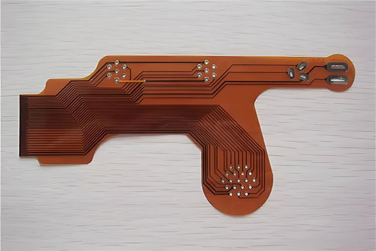
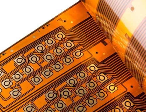
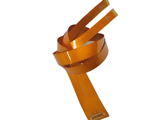
Double-sided Flexible Printed Circuit boards are a cornerstone of modern electronics, offering unmatched reliability and flexibility. Constructed using polyimide or polyester films, these circuits are characterized by their high wiring density, lightweight, thin profile, and excellent bending capabilities. This guide delves into the key aspects, materials, testing, and standards associated with double-sided FPCs, providing detailed insights for engineering professionals.
Overview of Double-Sided FPCs
Double-sided FPC flexible circuit boards are made from flexible insulating substrates such as polyimide or polyester film. They offer high reliability and exceptional flexibility, making them essential in various electronic products.
Key Features and Applications
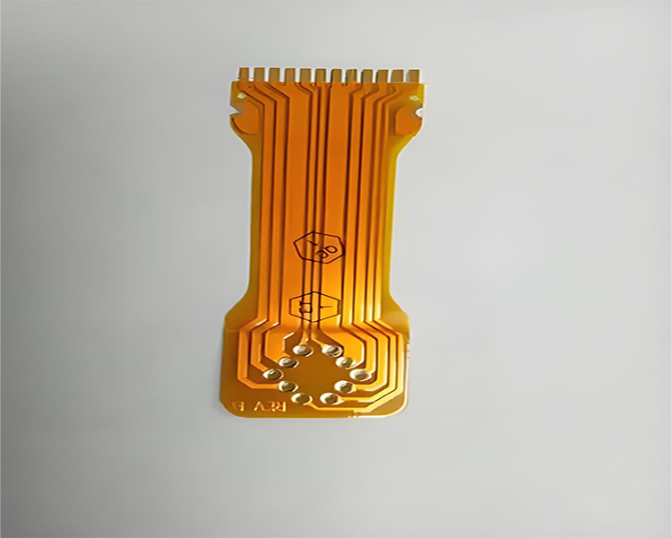
Double-sided FPCs boast high wiring density, lightweight, thin thickness, and excellent bending properties. They are available as single-sided, double-sided, and multilayer boards. Flexible circuits primarily serve as connection points in electronic devices, offering numerous advantages:
– Elimination of Excessive Wiring: Enhances flexibility and simplifies assembly within limited spaces.
– Volume Reduction: Efficiently minimizes product size, improving portability.
– Weight Reduction: Decreases the final product weight, enhancing user convenience.
Basic Materials of FPCs
Coverlay
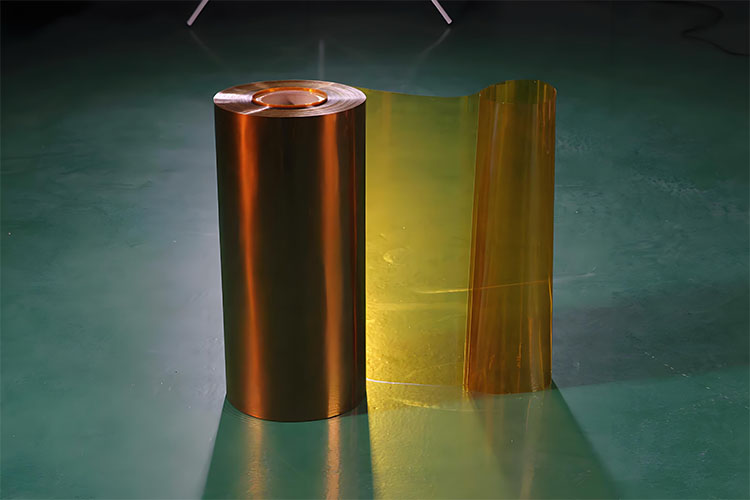
– Copper Foil: Electrolytic copper foil, rolled copper foil.
– Insulating Film: Polyimide, polyester.
– Adhesive: Various adhesive types for bonding.
Conductive Materials
– Protective Films with Adhesive: Polyimide coverlay, polyester coverlay.
– Solder Resist: Used to prevent solder bridging.
– Photoimageable Resins: Enhance precision and reliability.
Surface Conductive Coatings
– Metals: Tin, nickel/gold, silver.
– Others: Organic anti-oxidants, flux.
Reinforcement Materials
– Reinforced Insulating Film: Enhances durability.
– Insulating Boards: Provide additional structural support.
– Metal Plates: Strengthen the FPC structure.
– Adhesives: Secure various layers and components.
Interlayer Connection Materials
– Copper Plating: Ensures reliable electrical connections.
– Conductive Paste (Adhesive): Facilitates interlayer connectivity.
Testing Scope and Methods
Test Range
Tests encompass single-sided, double-sided, and multilayer flexible circuits. Flexible circuits referenced in this standard are based on polyimide (PI) or polyester (PET) substrates, including adhesive (3L-FCCL) and non-adhesive (2L-FCCL) types.
Testing Objectives
The primary aim is to establish a general rule for judging the appearance quality of flexible circuit boards. By doing so, it aids in the enhancement of manufacturing technology while minimizing resource wastage and environmental pollution.
Testing Methods
Visual inspection, magnifiers, and rulers are the primary tools, with additional instruments employed as necessary.
Quality Standards for FPCs
PCB Standards Overview
Standards are criteria for measuring quality. PCB standards include international, national, industry, and corporate standards, covering fundamental, design, material, finished product, testing, and assembly standards.
Specific FPC Standards
– International IEC Standards:
– IEC 60326 – 7 (1989): Non-through-hole single and double-sided flexible circuits.
– IEC 60326 – 8 (1989): Through-hole single and double-sided flexible circuits.
– IEC 60326 – 9 (1991): Flexible multilayer circuits.
– IEC 60326 – 10 (1991): Rigid-flex double-sided circuits.
– IEC 60326 – 11 (1991): Rigid-flex multilayer circuits.
Surface Appearance of Base Film
The allowable defect range for the base film surface is listed in the table. Additionally, no other defects, such as depressions, wrinkles, or foreign matter, that could affect usage are permitted.
Appearance of Coverlay
Defect ranges for overlay and coating appearances are specified below. Defects like depressions, wrinkles, or delamination, which could impact usability, are not allowed.
Pad and Coverlay Alignment
The deviation \(e\) of the pad and overlay must be within ±0.3mm for sizes under 100mm and within ±0.3% for sizes over 100mm.
Adhesive and Coating Flow
The flows \(f\) of adhesive and coating should be less than 0.2mm. However, at the pad location, considering overlay deviation and punching deviation, the minimum ring width \(g\) must still be ≥0.05mm.
Conductive Layer Discoloration
After undergoing a humidity test at 40℃ and 90% relative humidity for 96 hours, the conductive layer under the overlay must still meet the voltage, bending, folding, and soldering performance requirements.
Coating Omission
The conductor of the omitted coating should not accumulate solder, according to solderability requirements.
Poor Plating Adhesion
The plating layer must not exhibit delamination. The width \(W1\) and length \(L\) of the poor adhesion area, and the processed conductor width \(W\), must not affect the reliability of the contact area.
Storage Guidelines for Flexible Circuit Boards
The exposed conductors of FPCs require surface plating (anti-rust treatment) such as gold, OSP, tin, etc. The storage environment should avoid corrosive gases and maintain a temperature of 20±5℃ with relative humidity below 70%. Under these conditions, the effective storage period is six months post-manufacture.
Conclusion
Double-sided Flexible Printed Circuit boards are integral to modern electronics, providing flexibility, reliability, and efficiency. Understanding their materials, testing, and standards ensures optimal performance and longevity. By adhering to proper storage guidelines, the quality and functionality of FPCs can be maintained, supporting their crucial role in advancing electronic technologies.



Leave A Comment