Frequently Asked Questions

Company & Product Facts

  • Definition: Established in 2008, Gekunflex specializes in flexible and rigid-flex PCB manufacturing.
  • Parameters: ISO 9001,  1-24 layers; min trace/space 2/2 mil; max board size 500x1200mm.
  • Advantages: Quick-turn prototypes, high-mix low-volume production, and one-stop assembly.
  • Application Scenarios: Automotive, medical, aerospace, and consumer electronics.

Flexible PCB FAQ

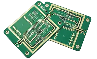
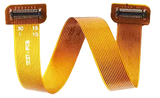
The only difference between a flexible circuit board and a rigid circuit board is the substrate material. The flexible circuit boards can be bent and folded, while the rigid circuit boards cannot.
Flexible Circuit

Rigid Circuit

Rigid Circuit

Rigid Circuit

A flexible circuit board of bent and folded flexible substrate material, used for application of flexibility or limited space.

The only difference between a flexible circuit board and a rigid circuit board is the substrate material. Flexible circuit boards can be bent and folded, while rigid circuit boards cannot.

The Process of Manufacturing Flexible Circuit Boards: The manufacturing process of flexible circuits primarily involves preparing the substrate, followed by designing the graphics, etching, drilling, plating, laminating copper, and finally assembling.

Take a look at the advantages of flexible circuit boards; they include excellent flexibility, thinness, lightweight, bendability, foldability, complex shapes and limited-space applications.

Higher manufacturing costs, low durability, and exceedingly low thermal conductivity.

Flexible circuit boards are made to be reliable; controlled manufacturing processes, dependable soldering and interconnection methods, and strict inspection and testing protocols guarantee their reliability.

Choosing appropriate materials for flexible circuit boards requires analyzing application requirements, environmental conditions, temperature ranges, reliability requirements, and selected substrate material, copper layer thickness, and lamination structure.

From designing and laying out the graphics and then transferring, etching, drilling, plating, and assembling the components of printed circuit boards (PCBs)

In printed circuit boards, design specifications ensure the correct dimensions, routing rules, spacing, layer structure, and material selection to ensure the functionality, manufacturability, and reliability of the circuit board. Signal integrity, thermal management, and electromagnetic compatibility must also be taken into account.

Rigid-Flex Board Questions

A rigid-flex board is a single printed circuit board that combines rigid FR-4 sections with flexible polyimide sections in a single laminated structure. The rigid portions hold components and connectors, while the flexible portions act as integrated “cables” that route signals between rigid sections. This eliminates connectors and cables, reduces weight, and enables 3D packaging.

Rigid-flex combines both rigid and flexible circuits in one integrated board, providing structural stability where components are mounted while offering flexibility where needed. Pure flex PCBs contain only flexible layers and are designed solely for dynamic flexing applications. Rigid-flex is typically used when you need component support in some areas and bending in others, whereas flex PCBs are used when the entire board needs to flex.

The minimum bend radius depends on whether the application is static (one-time fold during installation) or dynamic (repeated flexing during use). For static bends, the minimum radius is typically 6× the total flex section thickness; for dynamic flexing, it is 10× to 12× the total flex section thickness. For example, a 0.2mm thick 4-layer flex section requires a minimum 1.2mm radius for static bends and 2.0mm for dynamic bends. Following IPC-2223 guidelines is recommended.

Rolled annealed (RA) copper is preferred for flexible areas that require repeated bending because it has better fatigue resistance and can withstand millions of flex cyclesElectrodeposited (ED) copper is suitable for static bends or standard applications. For dynamic flex applications, ½oz (17μm) rolled-annealed copper is recommended; for static flex, 1oz (35μm) is acceptable.

Vias should never be placed within the bend radius area or within 1mm (40mil) of the rigid-to-flex transition zone. Vias create rigid points that concentrate stress and can cause cracking. Best practices include: placing all vias in rigid sections whenever possible, using filled vias in flex sections if unavoidable, and staggering via placement to avoid creating rigid lines.

The most common materials include polyimide film for the flexible dielectric, rolled annealed copper for flex layer traces, FR4 laminate or high-Tg FR4 for rigid sections, prepreg for bonding, coverlay (polyimide film with adhesive) for protecting flex area circuits, and stiffeners for additional support in specific areas. Polyimide is used because it provides excellent heat resistance, flexibility, and dimensional stability

Rigid-flex PCBs typically cost 3× to 8× more than equivalent rigid boards. The higher cost is driven by: expensive polyimide materials (accounting for ~35% of cost), sequential lamination cycles (~25%), tighter manufacturing tolerances, specialized handling requirements, and longer production times. However, eliminating connectors, cables, and manual assembly steps can offset the higher PCB cost, and in reliability-critical products, reduced field failures often provide the largest hidden savings.

Rigid-flex boards are commonly used in devices where space is limited, wiring must bend, and long-term reliability is required. Typical applications include: smartphones and tablets, smartwatches and wearables, medical devices, aerospace electronics, automotive modules, cameras, industrial sensors, and portable electronics.

Static flex means the board is bent once during installation and remains in that position throughout its life (e.g., folded into an enclosure)Dynamic flex means the board is bent repeatedly during normal use (e.g., a folding phone hinge or moving printer head). Dynamic flex requires more robust design choices: rolled-annealed copper, larger bend radii, thinner flex layers, and adhesiveless materials. Static-flex design rules cannot be safely applied to dynamic applications.

Failures most often occur near the rigid-to-flex transition interface, not in the middle of the flex area. Common failure causes include: stress concentration at the transition zone, inadequate strain relief, improper copper selection, tight bend radius, thick copper in bend areas, poor coverlay design, weak lamination, and incorrect adhesive selection. The transition zone is the most failure-prone area of any rigid-flex design and requires explicit attention during design review.