
Rigid PCB vs Flexible PCB: Best Choice for Your Applications
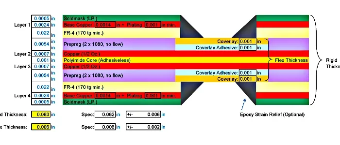



Choosing between rigid PCB vs. flexible PCB comes down to motion, space, and cost.
The difference starts at the base material: FR-4 glass-reinforced epoxy on one side, polyimide or PET film on the other. Almost every other gap — heat resistance, dielectric constant, thickness uniformity, bend life, lead time, price — follows from that first choice.
This rigid vs flex PCB comparison covers material, electrical and mechanical performance, thermal limits, cost, reliability, and the applications where each type wins.
What Are Rigid and Flexible PCBs?
Start With the Material: Polyimide vs FR-4
FR-4 is a woven glass cloth saturated with epoxy. It is stiff, inexpensive, dimensionally stable, and stocked in many thicknesses and Tg grades. Polyimide (PI) is a polymer film, usually 12.5 to 50 µm thick, laminated with or without adhesive. Three properties drive nearly every downstream difference:
- Heat resistance. Standard FR-4 has a glass transition temperature (Tg) around 130–180 °C. Polyimide film holds continuous service above 200 °C and does not soften at solder reflow temperatures. That is why flex survives reflow and hot compartments that would distort a thin rigid core.
- Dielectric constant. FR-4 sits near Dk 4.2–4.8 with Df 0.015–0.025. Polyimide is lower, near Dk 3.4–3.9 with Df 0.002–0.008. Lower Dk and Df mean less signal loss at high frequency and a thinner dielectric for the same controlled impedance.
- Thickness uniformity. FR-4 is press-laminated, so thickness varies across the panel and at copper edges, often ±10%. Cast polyimide film is tighter, ±5% or better before lamination. That helps impedance repeatability and predictable bend behaviour.
Once you accept the material gap, the rest of the comparison — bend radius, layer count, current capacity, price — is a consequence, not a separate argument.
Flexible PCBs
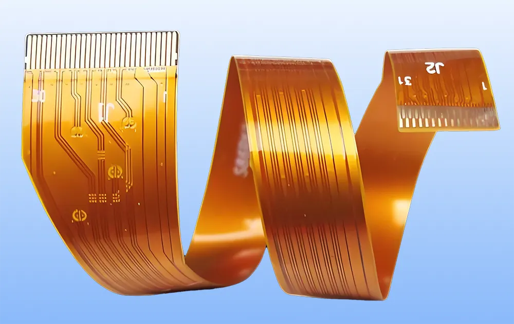
Flexible PCB
Flexible printed circuit boards sit on a bendable base film. Polyimide and PET are the common choices. Manufacturers laminate conductors between these films, so the board is wired and flexible at the same time. As a result, it can fold into a hinge or wrap around a battery.
Rigid PCBs
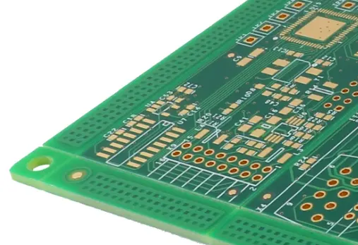
Rigid PCB
Rigid boards use FR-4, a glass-reinforced epoxy. The material does not bend. It gives a stiff platform for heavy parts and fixed mounting. For example, most large industrial and consumer products still rely on it.
Market context
Market analysts expect the global PCB market to keep growing, with flex circuits growing faster than traditional rigid boards as wearables, automotive sensors, and compact medical devices expand.
Rigid PCB vs Flexible PCB: Side-by-Side Comparison
This rigid vs flex PCB comparison table covers electrical, mechanical, thermal, and supply-side points. Values are typical ranges; confirm the exact stack-up with your fabricator.
| Factor | Rigid PCB | Flexible PCB |
|---|---|---|
| Base material | FR-4 glass-reinforced epoxy | Polyimide (PI) or PET film |
| Dielectric constant (Dk / Df) | ~4.2–4.8 / 0.015–0.025 | ~3.4–3.9 / 0.002–0.008 |
| Electrical performance | Stable impedance on thick cores; higher loss as frequency rises | Lower loss, thinner dielectric, tight impedance on thin film |
| Thickness uniformity | Press-laminated, roughly ±10% | Cast film ±5% or better; final stack depends on adhesive and coverlay |
| Mechanical flexibility | None — fixed and flat | Bends and folds; static and dynamic grades |
| Layer count | 1–20+ common; HDI far higher | 1–6 common, 10+ at advanced fabs; rigid-flex goes higher |
| Minimum trace/space | 3–4 mil standard, 2 mil in HDI | 2–3 mil typical, 1.5 mil on advanced lines |
| Component support | Strong; carries heavy parts and large connectors | Light parts only; stiffeners needed for connectors and BGAs |
| Thermal management | Good spreading on thick cores; thermal vias are routine | Thin, low mass — heat spreads poorly without a stiffener or metal backing |
| Current carrying | 1 oz Cu, roughly 1 A per mm width at 10 °C rise | Derate 20–30% at the same copper weight unless copper is heavier |
| Bend/flex life | Not applicable | Static: a few installation bends. Dynamic: 10⁵–10⁶+ cycles with rolled annealed copper at a generous radius |
| Unit cost | Lower per square inch | Higher per square inch |
| Tooling and MOQ | Low tooling, low minimum order | Higher setup and minimum order value |
| Lead time | Prototype 3–7 days; production about 2–3 weeks | Prototype 5–10 days; production about 3–5 weeks |
| Assembly | Connectors, harnesses, and hardware often added | Fewer connectors; stiffener and coverlay steps added |
| Testing | AOI, flying probe or bed-of-nails, impedance coupons | AOI plus dimensional, adhesion, bend, and dielectric-withstand checks |
| Best fit | Fixed mounting, heavy parts | Moving, small, weight-critical |
Each row links back to the same question: does the product move? If yes, flex usually earns its higher board price.
Flexible PCB vs Rigid PCB Cost: Look Past the Unit Price
Flex circuits usually cost more per square inch to fabricate. However, the unit price is only one line on the quote. Total cost also covers connectors, wire harnesses, mounting hardware, and assembly steps. A flex part can fold those parts into one piece.
Therefore, a higher board price may still lower the finished product cost. In addition, ask suppliers about NRE, tooling, MOQ, and expected assembly yield. A flexible PCB vs rigid PCB cost review should compare total cost of ownership, not one board price.
If you need a custom layout, request a Custom Flex PCB quote early so the cost drivers show up during design.
Where Flex Wins and Where Rigid Wins
Flexible PCB applications usually share three constraints: space, weight, and motion.
- Wearables: fitness trackers, smartwatches, and medical patches keep their shape with flex circuits.
- Automotive: flex parts fit engine compartments where space is tight, and temperatures are high.
- Medical: single-use endoscopes and portable diagnostic tools use ultra-low-profile substrates.
- Drones and aerospace: flex circuits cut weight and resist vibration.
- Consumer electronics: smartphones, laptops, and foldable screens rely on them.
Rigid boards win elsewhere. They carry heavy components, hold tight tolerances on a flat plane, and mount into fixed positions. Also, they are easier to rework when a prototype changes. For demanding programs, see the work on High-Reliability Flexible Circuits for High-End Applications.
Design Rules That Change the Decision
A flex design is not a rigid design printed on film. Three constraints decide whether flex is practical.
1. Static or dynamic bend. A part that bends once at assembly is easier than one that flexes for years.
2. Bend radius. Copper and coverlay must survive the tightest fold in the product.
3. Stiffeners and openings. Component areas often need stiffeners, and coverlay openings need clean edges.
Process choice matters too. PCB Etching and PCB Lamination set trace quality and layer bond. On mixed builds, a clean PI Protective Film step protects flexible areas during pressing. Teams planning a mixed board can review Rigid-Flex PCB Technology before they commit. For stack-up and process questions, our PCB Manufacturing FAQ covers common cases.
Reliability: Bend Life, Thermal Cycling, and Flame Rating
Flex and rigid fail for different reasons, so the reliability comparison has to be split.
- Bend life. Static flex (bent once during assembly) tolerates a radius near 6× total thickness. Dynamic flex (continuous motion) wants at least 10× and often 20–100× for high-cycle cables, with rolled annealed copper at ½ oz or less and traces routed perpendicular to the bend line. Grain direction and the neutral axis matter more than the nominal radius.
- Thermal cycling. Both types pass reflow, but rigid boards tolerate more rework cycles and more thermal mass. Flex is more sensitive to adhesive choice and to coverlay lift at stiffener edges after repeated cycling.
- Damp heat. 85 °C / 85% RH testing exposes adhesive systems in flex; polyimide film itself is stable, but the bond line is where moisture ingress starts. Rigid FR-4 handles humidity well but can show conductive anodic filament growth on tight-pitch, high-voltage designs.
- Flame rating. UL94 V-0 is the usual expectation for FR-4. Most polyimide constructions are inherently V-0, but the adhesive and coverlay system can change the result, so confirm the rating on the finished construction, not on the film datasheet. Board-level recognition typically falls under UL 796.
- Standards. IPC-6012 covers rigid boards, IPC-6013 covers flex, and IPC-2223 guides flex design. Thermal shock and humidity test methods are documented in IPC-TM-650. Ask suppliers which of these they actually build and inspect to, rather than which they list.
Heat and Current Carrying Capacity: The Numbers
Copper is the only meaningful heat path on either board type; polyimide conducts heat poorly, and FR-4 is only slightly better. What changes is the mass around the copper.
- A 1 oz (35 µm) trace about 1 mm wide carries roughly 1 A with a 10 °C rise on FR-4 in still air.
- On a 25–50 µm polyimide film with the same 1 oz copper, derate that by 20–30%. There is less laminate mass to spread heat and less surface area to convect from.
- You can recover capacity with 2 oz copper, a cross-hatched ground pour, a thermal pad, or a metal stiffener under the hot area. Those add cost and thickness, so budget for them at design time.
- Thermal vias are routine in rigid boards. In flex, they must be tented or filled, and they can crack if placed inside a bend zone — keep them on the stiff, non-bending section.
- Practical rule: size flex power traces by current first, then route. Keep high-current traces out of bend areas entirely.
A Scoring Table You Can Reuse
Score each row 0 (favours rigid), 1 (neutral), or 2 (favours flex), then add the column.
| Criterion | Question to ask | Weight |
|---|---|---|
| Motion in use | Does the board flex after assembly? | ×2 |
| Enclosure space | Is there no flat mounting plane available? | ×2 |
| Weight budget | Does every gram matter? | ×1 |
| Power level | Is current above ~1 A per trace? | ×2 |
| Layer count | Are more than 6 layers needed? | ×2 |
| Fine pitch | Are traces below 3 mil or spaces below 3 mil? | ×1 |
| Rework expected | Will prototypes be reworked repeatedly? | ×2 |
| Volume and schedule | Is a 3–5 week production lead time acceptable? | ×1 |
| Certification | Does the program need UL94 V-0 on a proven FR-4 stack? | ×1 |
A weighted total of 0–6 points points to rigid. 7–11 points means a rigid-flex or hybrid stack is worth quoting. 12+ means flex is the right starting point.
A quick decision path works the same way:
1. Does the board move in use? No → rigid. Yes → continue.
2. Is there space for a flat mounting plane? Yes → rigid or rigid-flex. No → flex.
3. Is current per trace above 1 A or layer count above 6? Yes → rigid-flex. No → flex.
4. Are prototypes likely to change? Yes → build rigid first, convert the flexing section in revision two.
Manufacturability and Supply Side: Lead Time, MOQ, and Inspection
The supply chain is often the deciding factor after the technical review.
- Supplier base. Rigid fabs are plentiful at every volume and technology level. Flex fabs are fewer, and advanced fine-line flex is concentrated in a much smaller group, so qualification takes longer.
- Lead time. Rigid prototypes run 3–7 days, and production takes about 2–3 weeks. Flex prototypes usually need 5–10 days because of tooling and coverlay setup; production runs 3–5 weeks. Rigid-flex adds another week or more.
- MOQ and NRE. Rigid orders can be small and cheap to start. Flex typically carries higher setup cost and a higher minimum order value, which matters most at prototype and low-volume stages.
- Testing differences. Rigid boards lean on AOI, flying probe or bed-of-nails, and impedance coupons. Flex adds dimensional checks, adhesion and coverlay bond tests, bend coupons, and dielectric-withstand checks after flexing. Expect to pay for those tests and to see them on the inspection report.
Common Misconceptions
- Flex does not mean you can bend it anywhere. Traces crack when a fold goes past the designed radius.
- Rigid does not mean thick. Thin FR-4 cores exist and work well in slim products.
- Unit price alone misleads. Connector, harness, and assembly savings can outweigh the board premium.
- Heat is not automatic. Flex removes weight, yet copper area still sets current capacity — and it usually needs derating, not credit.
- Lower Dk does not automatically mean a faster product. Termination, stack-up, and connector loss often dominate.
Which Should You Pick If You Are Still Unsure?
If the board stays fixed, has a flat place to mount, and carries parts heavier than a connector, start with rigid FR-4. It is cheaper, available from far more suppliers, easier to rework, and quicker to prototype. Choose flex only when a measurable constraint forces it — a fold, a moving joint, a thickness or weight limit you cannot meet otherwise.
If the design needs both, start rigid-flex so you design once and split the cost in later revisions. And if you are still undecided after the scoring table, build the rigid prototype first: prove the circuit on FR-4, then convert only the flexing section to polyimide.
Conclusion
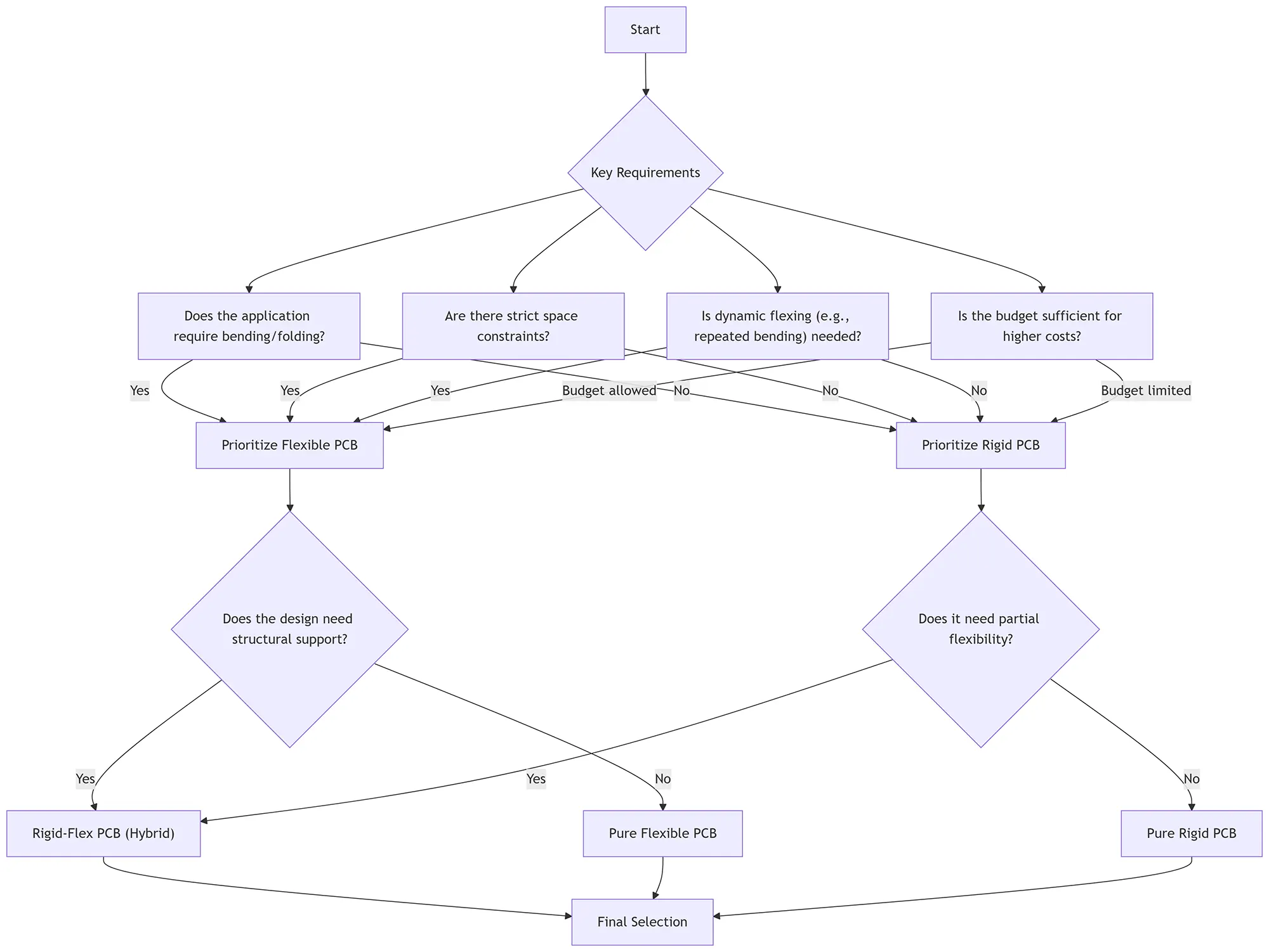
PCB Selection Flowchart: Flexible vs Rigid Design Decision Tree
Deciding between a flexible PCB and a rigid PCB depends on your specific needs. Designers use flexible PCBs in tight spaces and for moving applications. Rigid PCBs are better for stable and cost-effective environments. Rigid-flex PCB applications fill the gap by combining structural rigidity and design flexibility together.
Knowing where Flexible PCBs are used helps improve product life and the performance of many electronic devices. If you want to design a flexible PCB for your next device, consider a few key factors. First, consider the base material. Next, look at the conducting layers. Also, be aware of challenges like high temperatures and harsh environments. Doing so helps ensure your final electronic product is reliable, efficient, and future-ready.
FAQ
Is flexible PCB more expensive than rigid PCB?
Yes, at the board level. A flex circuit usually costs more per square inch than an FR-4 board. However, it can remove connectors, harnesses, and assembly steps. Therefore, the finished product cost can be lower even when the bare board costs more.
When should I choose rigid PCB over flexible PCB?
Choose rigid when the board stays fixed, carries heavy components, or needs a stiff platform. It also suits large flat layouts and prototypes that may still change. Choose flex when space, weight, or motion drives the design.
Can flexible PCBs handle high temperatures?
Engineers use polyimide flex in hot areas such as automotive engine compartments. Its base film handles heat better than many rigid laminates. However, copper weight and adhesive choice still set the real limit, so confirm the stack-up with your supplier.
Is a flexible PCB harder to manufacture and inspect?
Yes. Flex adds coverlay lamination, stiffener bonding, and dimensional control that rigid boards do not need, and inspection includes adhesion and bend checks rather than electrical test alone. Expect longer lead times and a higher minimum order value.
What bend radius can a flex PCB survive?
A static bend, made once during assembly, generally tolerates about 6× the total stack thickness. Continuous dynamic flexing wants 10× or more, and high-cycle applications often design for 20–100×. Copper type, copper weight, and trace direction relative to the bend line change the answer, so confirm with bend test data.
How many layers can a flexible PCB have?
Single-layer and two-layer flex are the most common and the cheapest. Four to six layers is routine for shielded or dense designs. Ten or more layers is possible at advanced fabricators but costs rise sharply, and rigid-flex is usually the better route once you pass that point.
Can you rework or repair a flexible PCB?
It is possible but riskier than on rigid FR-4. Polyimide handles localised heat well, yet the coverlay and adhesive around a reworked joint degrade faster, and repeated reflow can lift pads. Plan flex builds assuming limited rework and keep test points accessible.
What certifications and standards apply to each type?
Rigid boards are usually built and inspected to IPC-6012, flex to IPC-6013, with IPC-2223 governing flex design. Flame performance is commonly specified as UL94 V-0 on the finished construction, with board-level recognition under UL 796. Confirm the exact standard and rating a supplier builds to, not just what appears on a capability page.
Related Posts
- Flexible PCB & Rigid Flex PCB Etching Process — Related article
- PCB Lamination Process | Rigid & Flexible PCB Manufacturing Guide — Related article
- PI Protective Film Process for Rigid-Flex PCBs: Reducing Flexible-Area Cosmetic Defects – GekunFlex — Related article
- Flexible PCB: Features, Design Guide & Applications — Related article
- AI-Driven Optimization of Flexible Circuit Boards Production — Related article