
FPC Cable Guide
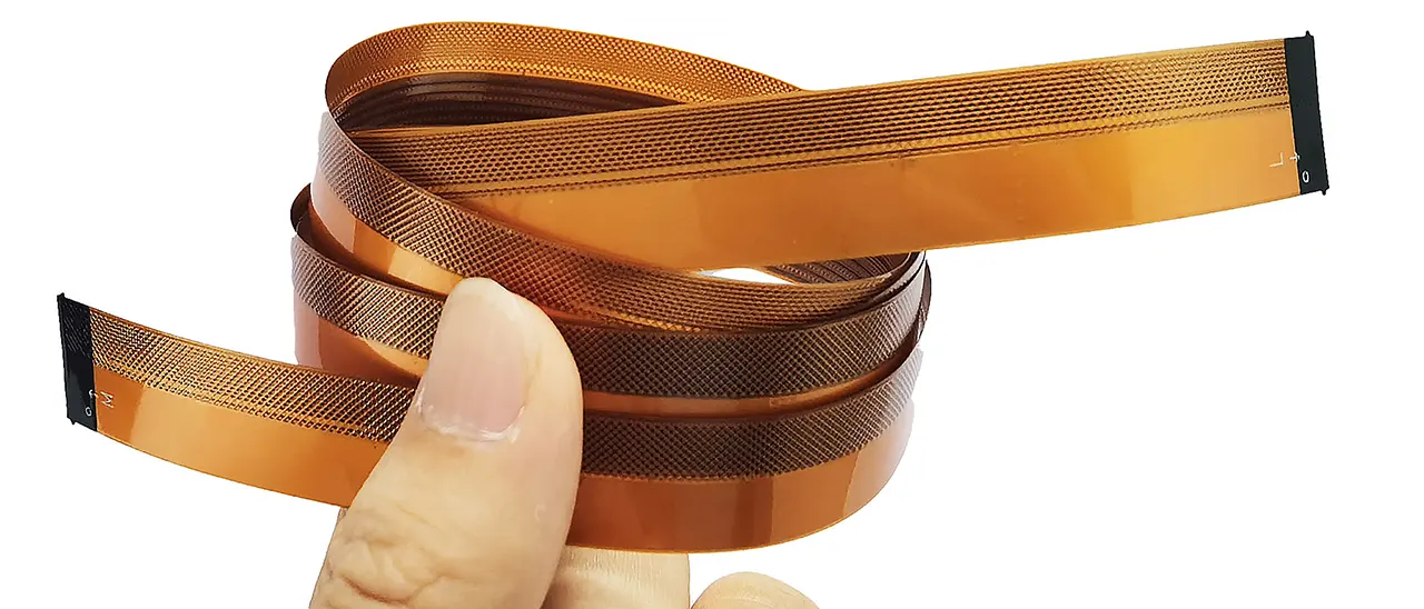
An FPC cable is a flexible printed circuit used as a bendable jumper between boards and modules. It carries copper traces on a thin polyimide or polyester base, so it can fold, twist, and bend without losing electrical integrity. This FPC Cable Guide covers FPC cable types, structure, connectors, and FPC cable applications.
What Is an FPC Cable?
FPC Cables, como circuitos impresos flexibles, son impresos en un sustrato aislante flexible como el poliéster o la poliimida, donde se graban senderos conductores como el cobre. FPCs can bend, twist, and fold without losing their electrical integrity. This is different from regular rigid PCBs, which can only bend a little. So, they are perfect for use in situations where space is scarce or movement is frequent.
Key Selection Criteria:
- Pitch Size (Distance Between the Centers of Conductors). Pitch sizes typically range from 0.15mm to 1mm or more. We can achieve a minimum of 0.1mm. A smaller pitch allows for higher density circuits, ideal for compact modules such as camera sensors or biometric readers. Choosing the wrong pitch could lead to connection failures or excessive EMI.
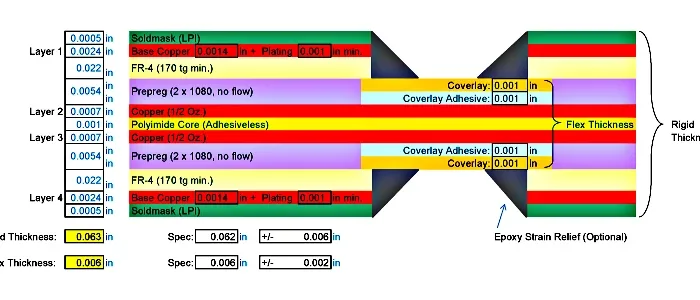
- Number of Conductors & Layers. Single-layer designs are common in the flat flex cables market because they are simple. However, double-sided and multilayer designs are important for devices that need multiple flat signal lines or grounding layers. Engineers should evaluate the current load, signal speed, and shielding needs.
- Front Flip and Back Flip Orientation. The connector’s mating side—whether front flip or back flip—must match the FPC cable’s pad location. People frequently overlook this subtle detail, which causes fit-together issues during prototyping or production.
- Bending Radius and Flex Cycles. If the application involves constant movement, such as printer heads or folding screens, you should rate the cable for bending. It should also have a minimal bend radius. Static flex cables work fine for stationary circuits with limited bends.
- Shielding and EMI Consideration. High-speed signals or sensitive analog lines require EMI protection. Engineers can opt for FPC cables with shielding films, ground mesh layers, or conductive adhesives to suppress noise.
FPC Cable Types and Tailoring Options
Gekun manufactures several FPC cable types tailored to specific application demands. Common variations include:
- Single-Sided FPC Cable – for simple signal transmission.
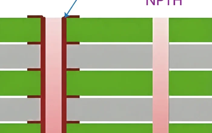
- Double-Sided with Vias – for bi-directional routing or grounding.
- Use multilayer FPC when space is limited, but circuit complexity is high.
- Stiffener-Supported FPC – adds rigidity at connector zones for improved insertion durability.
- Custom Die-Cut Shapes and Sizes – shaped to fit enclosures precisely without unnecessary overlaps.
These variations allow for flexible routing through tight assemblies and optimize signal integrity in complex designs.
How to Connect the FPC Cable Properly
The most common connection methods for FPC include:
- ZIF (Zero Insertion Force) Connectors. Easy to use and tool-free, ZIF connectors are ideal for prototyping and mass production. Proper insertion technique involves lifting the latch, inserting the flat flexible cable, and locking it to secure contact.
- BTB (Board-to-Board) Connectors.Used where rigid and flexible circuits interconnect. Engineers often prefer this for high-speed signal interfaces due to its compact footprint and shielding capability.
- Hot-Bar Soldering or ACF (Varies by direction: Conductive Film). Common in ultra-thin applications like OLED displays. These require precision machines and alignment fixtures during assembly.
- Adhesive-Based Connectors. Flexible printed circuits in some wearables or medical devices may use adhesive contacts or pressure connectors for quick connections.
Understanding the mechanical requirements and signal integrity needs is vital before choosing the connection method. Improper insertion force or a mismatched connector can damage the FPC connector or reduce its long-term reliability.
Common Issues and FPC Cable Repair Tips
FPC cable repair may not work well in high-volume applications. However, for development or small-batch builds, here are some important practices:
- You can often bridge trace breaks using silver conductive ink or copper tape with an insulation overlay.
- Pad Peeling apart: Avoid excessive reflow cycles; use localized soldering with controlled heat.
- Connector Wear: Replace worn ZIF connectors and ensure the distance between the centers of terminals aligns correctly.
- You can mitigate minor edge damage by using Kapton tape to reinforce the area.
These issues often result from improper installation, excessive bending, or high current stress. Preventive measures and training during assembly help reduce repair needs.
Electrical and Mechanical Specifications
Put measurable requirements on the FPC drawing so the sample and the production lot can be judged the same way.
For conductor resistance, state the allowed value per conductor at a given length and temperature, or use Ω/m; narrower and longer traces raise resistance and voltage drop.
For bend life, specify flex cycles at a defined bend radius and state whether the route is static or dynamic; dynamic routes need a larger radius and often a stiffener or rolled-edge design.
For temperature, polyimide FPCs commonly support -40°C to +125°C, while polyester constructions have a narrower range, so soldering and industrial exposure should be checked against the chosen material.
For impedance and shielding, high-speed or sensitive analog lines may need controlled impedance, such as 50 Ω single-ended or 90–100 Ω differential, plus a ground or shield layer; low-speed power and static signals often need neither. These four values belong on the drawing, not only in an email thread.
FPC Cable Applications
FPC cable applications span almost every compact electronic product.
- Mobile phones – display FPC, side key FPC, sensor FPC and flip phone hinge FPC.
- Consumer electronics – LED face mask flex PCB and FPCA for laser caps.
- Medical devices – rigid-flex PCB assemblies for handheld instruments.
- Industrial automation, automotive and high-end equipment – internal jumpers in tight, moving assemblies.
In each case, the cable replaces a bundle of round wires and saves space. For handset work, see FPC for Mobile Phones. For broader design context, read the Flexible PCB overview and the Rigid-Flex PCB Technology notes.
Why Work with Gekun as Your FPC Cable Manufacturer
At Gekun, we don’t just make flexible circuit cables. We create solutions that fit your product’s real needs. Whether you need flat flex cables in standard sizes or custom flex cables for small spaces, we can help:
- Tailored Engineering Support for design and prototyping.
- Precision Manufacturing with quality assurance checks at every stage.
- High-Reliability Materials, including polyimide films, plated copper, and PET-based insulation for better thermal performance.
- Global Supply Chain Optimization, ensuring cost-effective scaling and fast lead times.
Our experience serving demanding applications makes us one of the trusted FPC cable manufacturers globally. We work with product teams from the idea stage to mass production. Ensure your interconnects enhance performance, not hinder it. Also offer flexible Tailoring.
FFC and FPC Cable – Which One to Choose?
Though both FPC and FFC cables are used in compact electronics, they differ significantly:
- FFC (Flat Flexible Cable): Pre-formed flat cables with parallel conductors laminated between PET insulation. These are ideal for low-cost, standardized applications—simple, low-tailoring.
- FPC (Flexible Printed Circuit): Custom-etched circuits on flexible substrates, supporting multiple layers and tighter bends.
If your design calls for a standardized layout and low-cost, flat flex cables (FFC), they may be sufficient. However, for complex signal routing, high reliability, or 3D integration, FPC is the superior choice.
We go deeper into this in our dedicated FFC vs FPC comparison page — be sure to check it out.
Conclusion
FPC cables are very flexible. They offer many design options and save space. You can use them for new wearable medical devices or durable automotive sensor systems.
Procurement professionals and engineers can make better choices. They can do this by learning about different cable types, connector options, repair methods, and their specific needs. These choices can lower costs, boost reliability, and speed up time to market.
For expert advice or to request a custom cable sample, contact Gekun—your partner in advanced flexible circuit solutions.
FAQ
What are the most common FPC cable applications?
FPC cable applications include mobile phone displays and hinges, camera and biometric modules, consumer devices, medical handhelds, industrial automation and automotive internals. In all of them, the cable bends inside a tight enclosure and replaces round wire bundles.
How do I choose pitch and conductor count?
Start with the connector already on the board. Pitch sizes usually run from 0.15 mm to 1 mm or more, and a smaller pitch gives higher density. Common connector references are 0.5 mm for dense display or camera tails, 1.0 mm for general board jumpers, and 1.25 mm for more robust handling. Then count the signals and grounds your design needs. Add layers only when one layer cannot carry the routing.
How do I estimate bending radius and flex life?
Check whether the cable moves or stays fixed. Static circuits tolerate limited bends, so a simple single-sided cable is enough. For constant movement, such as printer heads or folding screens, specify a rated bend radius and flex-cycle count. Put the cycle count, bend radius, and test method on the drawing so the sample and production test use the same basis.
What electrical and mechanical specs should be on an FPC drawing?
At minimum, list conductor resistance or allowed voltage drop, bend cycles at a defined radius, temperature rating, and any impedance or shielding requirement. For high-speed lines, add controlled impedance and a ground or shield layer; for low-speed power routes, those may not be needed. These values should be measurable and tied to the reliability test plan.
What is the difference between an FFC and an FPC cable?
An FFC is a flat flexible cable made from parallel conductors. An FPC is an etched flexible circuit on polyimide or polyester. FPC cables support vias, multiple layers, stiffeners, and die-cut shapes, so they fit more complex routing.
Related Posts
- Flexible PCB: Features, Design Guide & Applications — Related article
- Closed-Loop Recyclable Flexible PCB Manufacturing Guide — Related article
- EMI Shielding Method for FPC and Flex Circuits Guide — Related article
- FPC Bending Resistance: Design Guide for Flex Circuits — Related article
- FPC Design Guide — Related article