
EMI Shielding Method for FPC and Flex Circuits: Complete Guide
EMI Shielding Method for FPC and Flex Circuits: Complete Guide
An EMI shielding method is a material or design technique that blocks, reflects, or absorbs electromagnetic interference around a circuit. For flexible circuits, the most common methods are laminated EMI shielding film, a copper shield layer or shielding network, and conductive cloth or tape applied to the FPC. This guide compares these options and explains how to select, design, and validate an EMI shielding method for commercial FPC projects.
What Is an EMI Shielding Method?
An EMI shielding method reduces radiated and conducted noise that could disturb a circuit or violate EMC limits. It works mainly by reflection, absorption, and grounding. Flexible circuits are thin, bendable, and often placed near antennas, displays, batteries, and high-speed connectors. Therefore, the shielding method must control interference without breaking bend life or adding too much thickness.
Core EMI Shielding Methods for Flexible Circuits
1. Laminated EMI Shielding Film
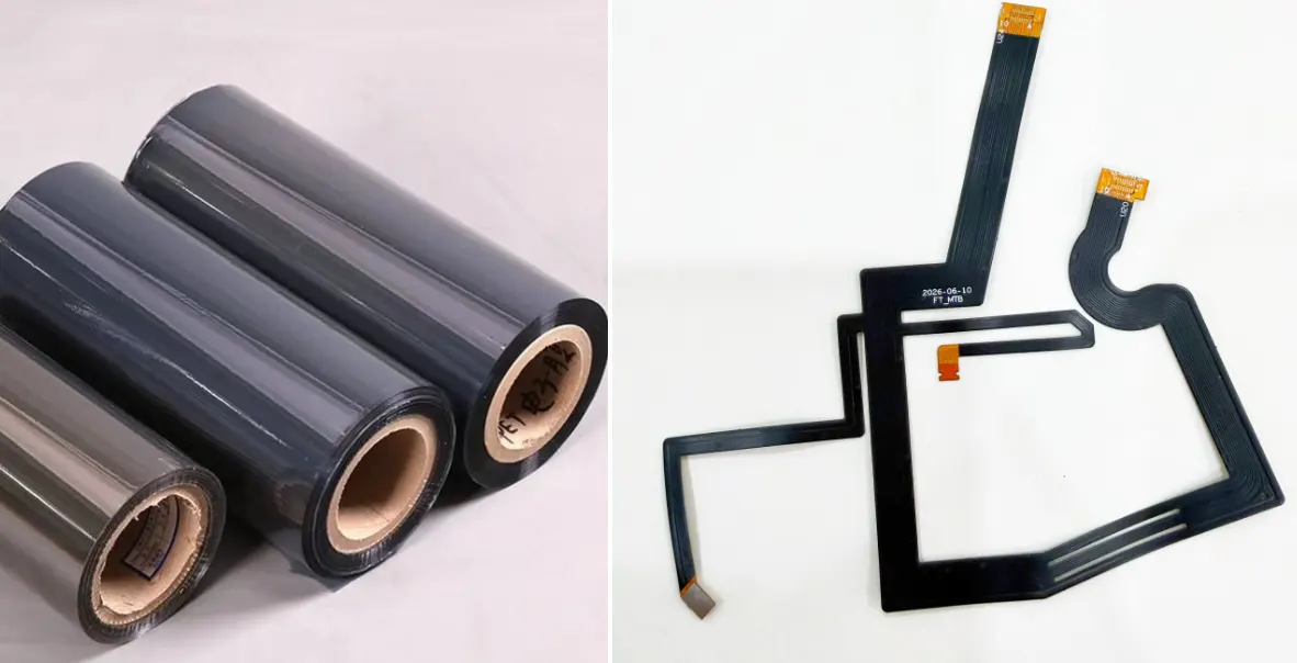
Laminated EMI Shielding Film
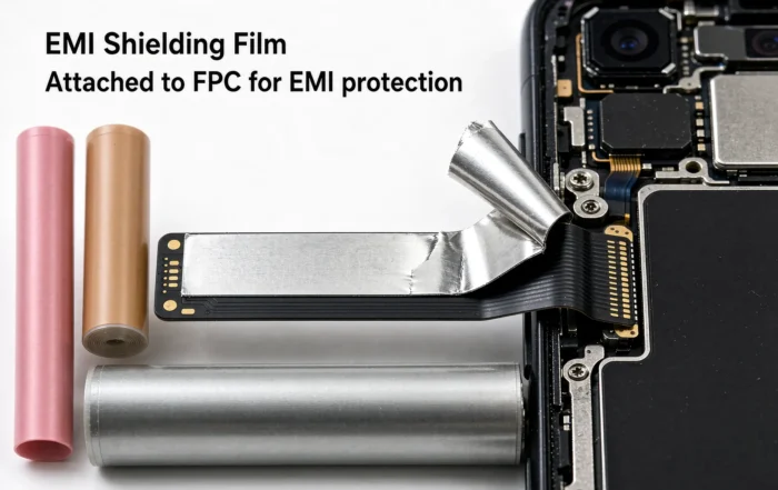
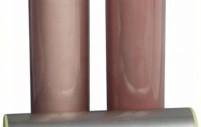
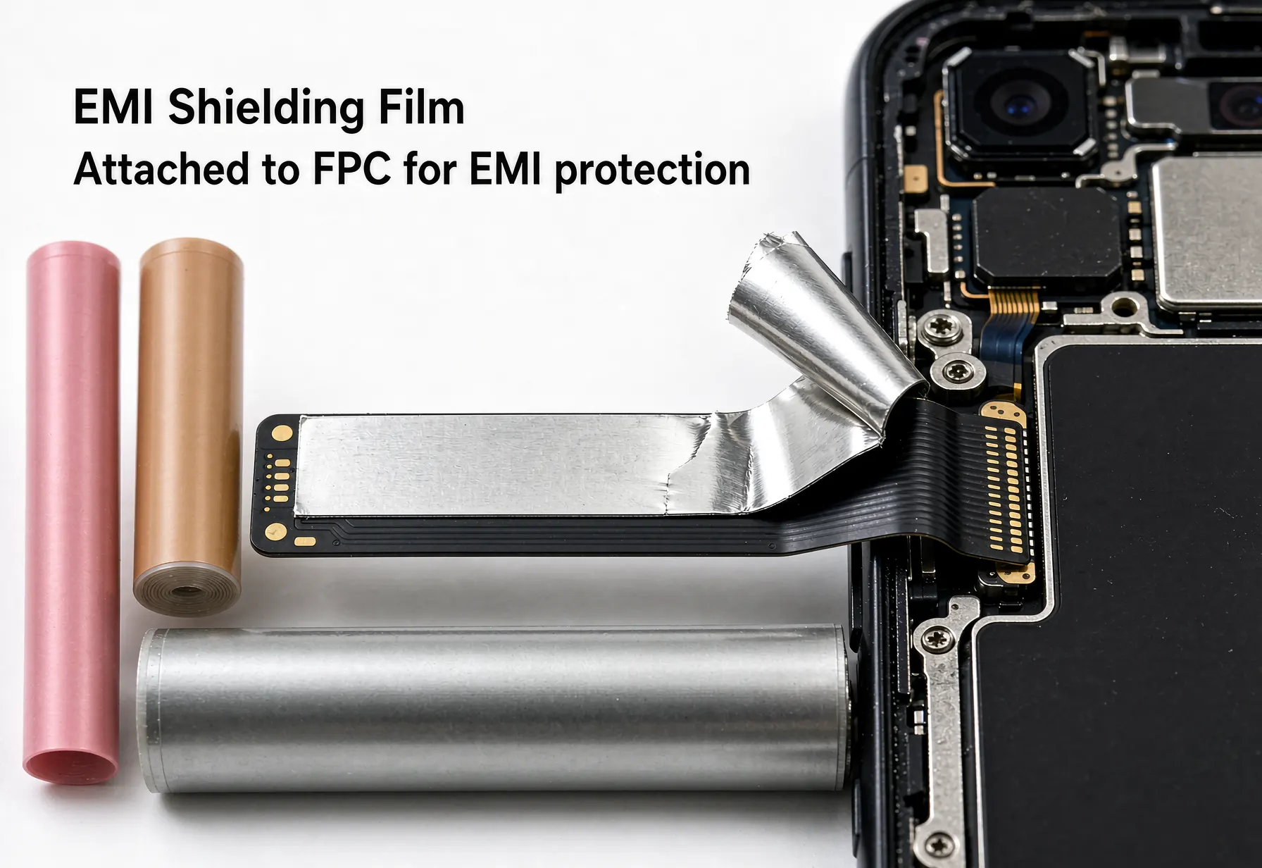
EMI shielding film is laminated over the FPC surface. It usually combines a conductive layer, adhesive, and insulating cover. The film can provide about 25–60 dB, depending on grounding quality and frequency. It is a strong fit for slim devices such as cameras, wearables, and display modules. However, adhesion, bend radius, and lamination pressure must be controlled.
2. Shield Layer or Shielding Network in the FPC Stack
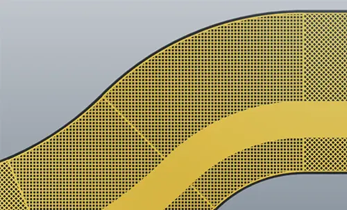
Shielding Network in the FPC Stack
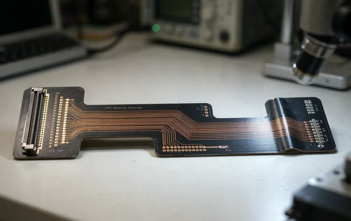
A shield layer is built into the flexible circuit stack. It can be a solid copper pour, a cross-hatch mesh, or a shielding network with ground vias. This method often reaches 40–90 dB and works well for high-speed and RF designs. It also adds layers, weight, and cost. For a deeper review, see Flexible Circuit Shielding design guidance.
3. Conductive Cloth, Fabric Tape, and Conductive Foam
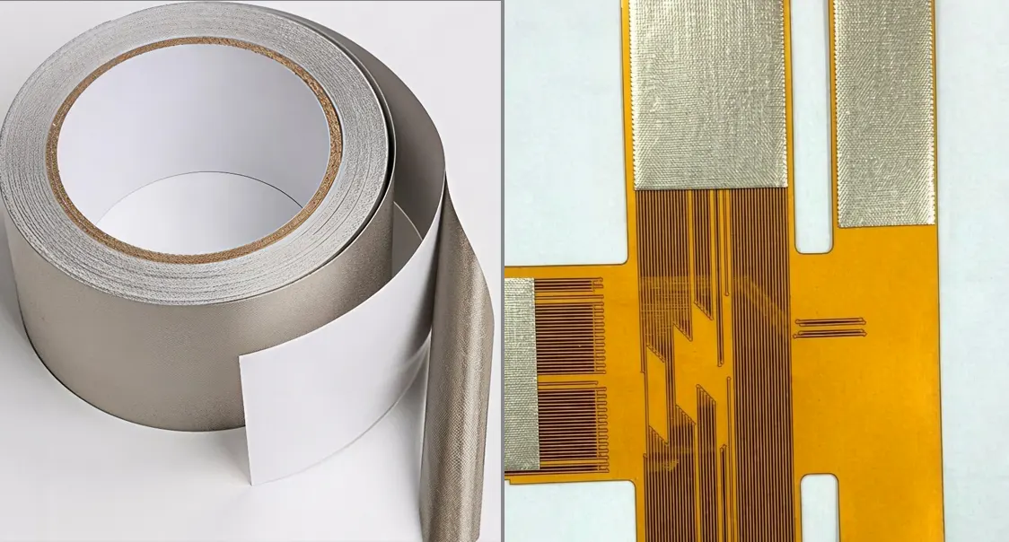
Conductive Cloth works in FPC
Conductive cloth and fabric tape are applied to an FPC, a connector, or an enclosure gap. They typically provide 30–70 dB and are useful for local repair, grounding, and shielding around openings. The main risks are adhesive aging, uneven pressure, and poor contact resistance. Add a conductive adhesive or pressure-sensitive tape only after testing.
4. Silver Ink, Conductive Coating, and Board-Level Shields
Silver ink and conductive coatings can shield thin areas with 20–50 dB. Board-level shield cans can reach 40–80 dB, but they are rigid and may need a stiffener. These options suit component-level shielding, small modules, and prototypes. They are less flexible than EMI film or a shield layer.
EMI Shielding Method Comparison
| Method | Typical shielding effectiveness | Frequency fit | Cost impact | Best use | Watch-outs |
|---|---|---|---|---|---|
| Laminated EMI film | 25–60 dB | DC–6 GHz; some to 10 GHz | Medium | Slim FPC, camera, wearable | Adhesion, flex cracks |
| Copper shield layer or network | 40–90 dB | DC–10 GHz+ | Medium–high | High-speed, RF, automotive | Layer count, bend life |
| Conductive cloth or tape | 30–70 dB | 30 MHz–6 GHz | Low–medium | Local grounding, connector gaps | Adhesive aging, pressure |
| Silver ink or coating | 20–50 dB | DC–3 GHz | Medium | Thin coating, small runs | Cracking, resistivity |
| Board-level shield can | 40–80 dB | DC–10 GHz+ | Medium | Components, modules | Height, rework |
These values are typical ranges, not guarantees. Real performance depends on grounding, apertures, material thickness, and test setup. Always validate the final assembly.
How to Choose an EMI Shielding Method
1. Define the EMC target. Confirm the standard, frequency range, and required margin.
2. Locate the noise path. Check clocks, power planes, connectors, cables, and antennas.
3. Match the method to space and bend needs. Use film for thin profiles and a shield layer for high isolation.
4. Plan the ground return. A shield without a low-impedance ground can make emissions worse.
5. Build a prototype and test. Compare near-field scans before and after shielding.
Use this simple decision guide:
- Need thin profile and moderate isolation: choose laminated EMI film.
- Need high isolation at GHz frequencies: choose a shield layer or shielding network.
- Need a local fix or connector gap seal: choose conductive cloth or tape.
- Need component-level isolation: choose a board-level shield can.
- Need low cost first: compare film and cloth, then review flexible PCB cost factors.
Design and Manufacturing Checklist
- Keep the ground return path continuous under high-speed traces.
- Stitch the shield layer with ground vias. For >1 GHz, spacing of 3–5 mm or less is common.
- Terminate the shield at the flex circuit connector with 360° contact when possible.
- Avoid long slots, cuts, or splits in the shield. They act as antennas.
- Use coverlay openings and conductive adhesive to create stable ground contact.
- Control lamination temperature, pressure, and cure time for EMI film.
- Test bend life after lamination, not before.
- For automotive programs, follow FPC in Electric Vehicles design and test rules.
- If the design uses flat cable, review FFC vs FPC before locking the shield stack.
- Choose a supplier with proven high-shielding FPCB experience.
- Apply general Flexible Circuits design rules from the start.
Standards, Testing, and dB Targets
Common EMC standards include FCC Part 15 in the US, the CE EMC Directive 2014/30/EU in Europe, CISPR 11 and CISPR 32, and IEC 61000-4-3. Automotive programs often use ISO 11452 and CISPR 25. Test methods include near-field scanning, TEM cells, reverberation chambers, and anechoic chambers.
For reporting, record the shield resistance, frequency range, before-and-after dB, and test setup. A shield that adds 20 dB may be enough for one product and far too little for another. Therefore, set the dB target from the standard and the product risk, not from a generic number.
Common Failure Modes and Fixes
- Floating shield: add ground vias and verify DC resistance.
- Sparse vias: reduce via spacing, especially above 1 GHz.
- EMI film delamination: check adhesive, bend radius, and lamination profile.
- Conductive cloth dry-out: qualify the adhesive and pressure over time.
- Long shield slots: split, bridge, or reroute signals away from the gap.
- Ground loops: define single-point or controlled multi-point grounding.
- Thermal stress: pair shielding with thermal management. See Flexible Circuit Shielding for related design notes.
Supplier and Cost Evaluation for Commercial Projects
For a commercial project, evaluate the supplier on film lamination, laser via, shield layer etching, and conductive cloth assembly. Ask for IPC-6013, UL, RoHS, and REACH evidence. Request shielding test data, not just a material datasheet.
Cost depends on layer count, film type, via count, yield, and test level. EMI film and extra shield layers change flexible PCB price per square inch. Also review flexible PCB cost factors before you compare quotes. For high-volume programs, select a partner with high-shielding FPCB manufacturing experience. If you need a broader capability check, start with Flexible Circuits.
FAQ
Which EMI shielding method is best for flexible circuits?
There is no single best method. Laminated EMI film is best for thin, space-limited FPCs. A copper shield layer or shielding network is best for high isolation and high frequencies. Conductive cloth is best for local grounding and connector gaps. The right choice depends on your dB target, frequency, bend life, and budget.
Does EMI shielding film provide enough shielding for 5G or GHz signals?
EMI film can work at GHz frequencies, but performance depends on grounding and film structure. Many films provide 25–60 dB in typical FPC assemblies. For critical 5G, radar, or high-speed links, use a shield layer with dense ground vias and validate with board-level testing.
Can I add a shield layer to an existing FPC design?
Yes, but it may require a new stack-up, more layers, and new artwork. You must also add ground vias, update the coverlay, and recheck bend life. If the current design is tight, EMI film or conductive cloth may be a faster path.
How is shielding effectiveness measured?
Shielding effectiveness is measured in decibels by comparing signal strength with and without the shield. Common methods include near-field scanning, TEM cells, reverberation chambers, and anechoic chamber tests. The result is frequency-dependent, so always report the test range and setup.
What standards apply to EMI shielding?
Key standards include FCC Part 15, CE EMC Directive 2014/30/EU, CISPR 11, CISPR 32, and IEC 61000-4-3. Automotive products often follow CISPR 25 and ISO 11452. Your target market and product type decide which standards apply.
How does EMI shielding affect flexible PCB cost?
Shielding can add material, layers, vias, lamination steps, and testing. EMI film adds material and process cost. A shield layer adds layer count and via count. Conductive cloth adds assembly labor. These items are common flexible PCB cost factors, so quote them early.
Next Step
Send your stack-up, target dB, frequency range, and bend requirement to your FPC partner. A good supplier will propose an EMI shielding method, build a sample, and test it before mass production.
Related Posts
- FFC vs FPC: Key Differences and How to Choose — Related article
- Flexible Circuit Shielding, Thermal Management, and Stiffening — Related article
- High-Shielding FPCB Manufacturing: High-Current Methods — Related article
- EMI Shielding Method for FPC and Flex Circuits Guide | Gekun — Related article
- FPC in Electric Vehicles Guide — Related article





