
EMI Shielding Film for Flex Circuits: Material Types and Selection Guide
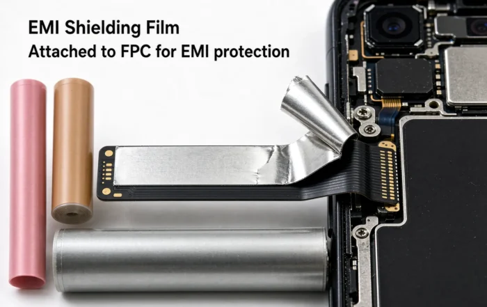
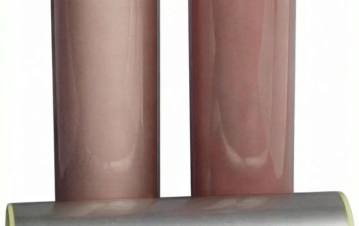
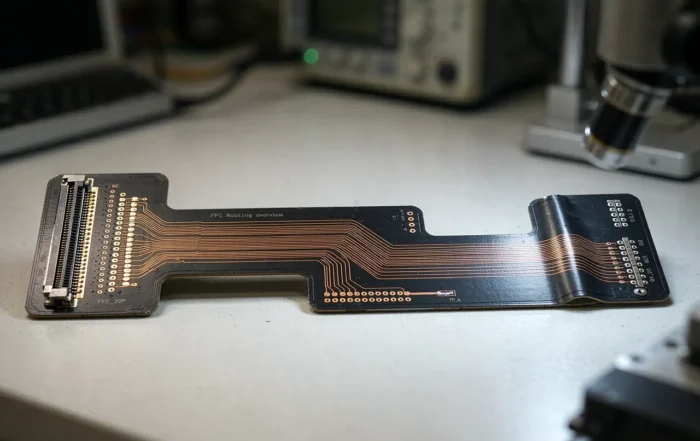
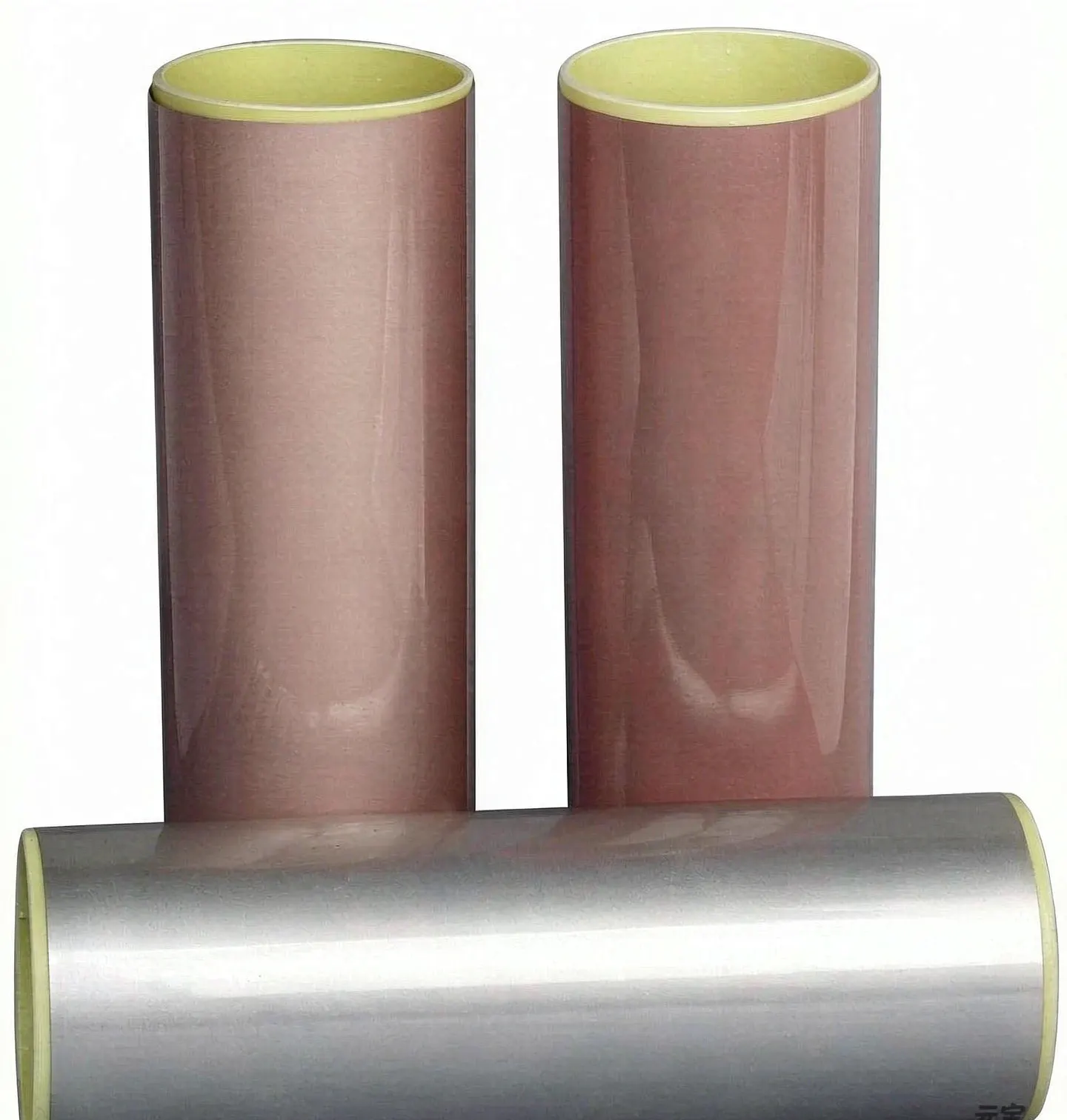
An EMI shielding film for flex circuits is a thin, flexible laminate that suppresses electromagnetic interference on FPCs and rigid-flex boards. It combines a conductive metal layer, a conductive adhesive, and a protective cover layer. Choose it by frequency, required dB, bend type, thickness, and reflow temperature.
Why EMI Shielding Film Matters in Flex Circuits
Flexible circuits are used in smartphones, cameras, wearables, automotive displays, and medical devices. As signal speeds rise, these thin boards can radiate noise or pick up interference. A metal shield can be rigid and adds height, so it does not fit tight enclosures. Therefore, engineers use an EMI shielding film that bends with the circuit. For broader design context, see Flexible Circuit Shielding.
In addition, shielding film helps pass EMC tests without changing the whole stack-up. It also protects sensitive traces from crosstalk. For many FPC programs, the film is the most practical way to combine electrical performance and mechanical flexibility.
What Is an EMI Shielding Film? Definition and Layer Structure
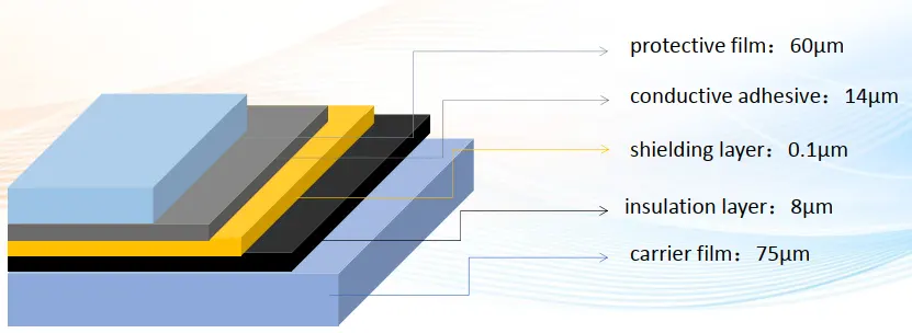
Layer Structure for EMI Shielding Film
An EMI shielding film is a laminated material that attenuates electromagnetic waves. It is bonded to an FPC surface, usually over the signal traces or the whole flexible area.
A typical film has four layers:
- Protective layer: PI or PET film that provides insulation and mechanical strength.
- Metal layer: silver, copper, nickel, or a metal composite that reflects and absorbs EMI.
- Conductive adhesive: bonds the film to the FPC and connects the metal layer to ground.
- Release liner: protects the adhesive before lamination.
The exact layer order depends on the supplier and the application. For related stack-up details, review flexible PCB material stack-up. Also, the outer protective layer is similar in function to a PI protective film, which reduces cosmetic defects in rigid-flex production.
How EMI Shielding Film Works in an FPC

EMI shielding film applied to FPC
Shielding film works through three main mechanisms: reflection, absorption, and grounding.
1. Reflection: The metal layer reflects incoming electromagnetic waves.
2. Absorption: Conductive particles or magnetic fillers convert some energy into heat.
3. Grounding: The conductive adhesive connects the metal layer to the FPC ground. This step is critical. Without a low-resistance ground path, the film becomes an antenna instead of a shield.
Common grounding methods include conductive adhesive to a ground pad, laser vias to inner ground planes, edge plating, and grounding tabs. In dynamic flex areas, the ground connection must survive repeated bending. Therefore, use a flexible conductive adhesive and avoid sharp copper edges.
Material Types of EMI Shielding Film for Flex Circuits
Material choice drives shielding performance, thickness, bend life, and cost. The main types are described below.
1. Metal Composite Film (Silver-Coated Copper Particles)
This film uses silver-coated copper particles in a polymer binder. It offers good conductivity and moderate flexibility. Typical shielding effectiveness is 60–80 dB from 100 MHz to 10 GHz. Thickness is often 25–50 µm. It is a common choice for static and mild dynamic flex.
2. Copper Foil Laminate
A copper foil laminate uses a thin copper layer with a conductive adhesive. It provides high shielding, often 70–90 dB. However, copper can crack after many bend cycles if the design is not optimized. Use it for static flex or low-bend areas. For high-current or high-shielding needs, see high-shielding FPCB.
3. Sputtered Copper/Nickel Film
Sputtered films deposit copper and nickel directly on a PI or PET carrier. They are thin, typically 12–25 µm, and offer 60–75 dB. They are suitable for compact designs. However, sputtered layers can be sensitive to handling and may need a protective coating.
4. Copper Grid PET Film
A copper grid on PET provides transparent or semi-transparent shielding. It is used for display windows and openings. Shielding effectiveness is lower, often 30–50 dB, because the grid has openings. It also transmits light. If your design uses PET substrates, compare options in PET vs FPC selection.
5. Carbon-Based and Hybrid Films
Carbon-based films are less conductive than metal films, with typical shielding of 20–40 dB. They are useful for low-frequency noise control and cost-sensitive projects. Hybrid films combine carbon with metal particles to improve performance. If you evaluate conductive carrier films, see carbon-coated film evaluation.
For conductor construction differences that affect routing and termination, see FFC vs FPC.
Shielding Effectiveness: dB, Frequency Range, and Test Methods
Shielding effectiveness (SE) is measured in decibels (dB). Higher dB means less energy passes through. A 60 dB shield blocks 99.9999% of the field. However, SE changes with frequency. Thin films often perform well from 100 MHz to 6 GHz, but performance can drop at very high frequencies.
Common test methods include:
- ASTM D4935: standard test for planar materials, often 30 MHz to 1.5 GHz.
- IEEE 299: system-level shielding test for enclosures.
- MIL-STD-285: older method for shielded rooms and enclosures.
- IEC 61000-4-3: immunity test, not a direct SE test.
For FPC films, request SE data at the frequencies your product uses. Also ask for test setup details, because fixture and grounding can change results.
Selection Guide: How to Choose the Right EMI Shielding Film
Use a step-by-step decision flow.
1. Define frequency and required dB. Start with the EMC target and the noisy frequency range.
2. Define flex type. Is the area static, dynamic, or flex-to-install? Dynamic flex needs a thin, ductile film.
3. Set thickness and stack-up limits. Check Z-height, cover layer thickness, and bending radius.
4. Choose the adhesive system. Conductive PSA is common; epoxy or thermoplastic adhesives may be needed for high temperature.
5. Select the grounding method. Use conductive adhesive, vias, or edge plating. Keep ground resistance low.
6. Validate with a prototype. Test SE, bend life, and environmental reliability before mass production.
Selection Matrix for Flex Applications
| Criterion | Silver-coated composite | Copper foil laminate | Sputtered Cu/Ni | Copper grid PET | Carbon-based |
|---|---|---|---|---|---|
| Typical SE | 60–80 dB | 70–90 dB | 60–75 dB | 30–50 dB | 20–40 dB |
| Thickness | 25–50 µm | 30–70 µm | 12–25 µm | 50–125 µm | 20–50 µm |
| Static flex | Excellent | Excellent | Good | Fair | Good |
| Dynamic flex | Good | Fair | Good | Poor | Good |
| Reflow 260°C | Good | Good | Good | Limited | Limited |
| Bend radius | 1–2 mm | 2–3 mm | 0.5–1.5 mm | 3–5 mm | 1–2 mm |
| Relative cost | Medium | Medium | High | Medium | Low |
| Best use | General FPC | High shielding | Thin devices | Display windows | Cost-sensitive |
The matrix is a starting point. Always confirm with sample tests.
EMI Shielding Film vs. Coating, Tape, and Shield Cans
| Option | Thickness | Flexibility | Repair | Cost | Best for |
|---|---|---|---|---|---|
| EMI shielding film | 12–125 µm | High | Moderate | Medium | FPC and rigid-flex |
| Conductive coating | 5–25 µm | High | Low | Low | Simple coverage |
| EMI tape | 30–100 µm | Medium | High | Low | Rework and small areas |
| Shield can | 1–3 mm | None | Low | Medium | Rigid PCB and modules |
Shielding film is usually the best balance for flexible circuits. Coatings are thinner but harder to ground and repair. Tape is easy to apply but less uniform. Shield cans give high isolation but add height and rigidity.
Cost, Reliability, and Common Failure Points
Cost depends on material, roll width, and volume. Silver composite films cost more than carbon films. Copper foil is cost-effective but less flexible. Therefore, match the material to the bend requirement.
Common failure points include:
- Cracking after repeated bending.
- Adhesive squeeze-out during lamination.
- High edge resistance or poor grounding.
- Corrosion after salt spray or humidity.
- Delamination after thermal cycling.
Validate with bend tests, 4-wire resistance checks, SE tests after bending, thermal shock from -40°C to 125°C, and salt spray. For rigid-flex, also review air-gap yield improvement for rigid-flex because air gaps can affect lamination pressure and film adhesion.
Supply Chain and Commercial Checklist
Before you release a purchase order, confirm:
- Roll width and length: common widths are 250–500 mm.
- MOQ: often 500 m² or one full roll.
- Compliance: RoHS, REACH, UL 94 V-0, and halogen-free options.
- Adhesive type and shelf life.
- Lead time: samples in 2–4 weeks, mass production in 4–6 weeks.
- Documentation: SE test report, COC, and material datasheet.
Also, request a sample with your actual stack-up. A film that works on a flat test coupon may fail on a dynamic FPC.
Frequently Asked Questions
What is EMI shielding film used for in flex circuits?
It reduces electromagnetic interference on FPCs and rigid-flex boards. It is bonded over traces or flexible areas and grounded to the circuit.
Which EMI shielding film has the best shielding effectiveness?
Copper foil laminates usually give the highest SE, around 70–90 dB. Silver-coated composite films offer 60–80 dB with better flexibility.
Can EMI shielding film survive dynamic bending?
Yes, if you choose a thin, ductile film and a flexible conductive adhesive. Sputtered Cu/Ni and silver composite films are common for dynamic flex.
How is shielding effectiveness tested?
Planar films are often tested with ASTM D4935. System-level assemblies may use IEEE 299 or MIL-STD-285. Request data at your product frequencies.
What thickness is typical for FPC shielding film?
Most films are 12–125 µm thick. Thin sputtered films are 12–25 µm, while copper grid PET films can be 50–125 µm.
Conclusion and Next Steps
Selecting an EMI shielding film for flex circuits is a balance of shielding dB, thickness, bend life, reflow tolerance, and cost. Start with frequency and grounding, then choose the material type, and validate with samples.
For a high-shielding FPCB or a custom film stack-up, send your layer stack, bend radius, and EMC target. Our team can recommend a film and provide samples for validation.
Related Posts
- FFC vs FPC: Key Differences and How to Choose — Related article
- High-Shielding FPCB Manufacturing: High-Current Methods — Related article
- EMI Shielding Method for FPC and Flex Circuits— Related article
- Carbon-Coated Film Evaluation for Reliable FCCL Copper Plating — Related article





