
Carbon-Coated Film Evaluation for Reliable FCCL Copper Plating
A Carbon-Coated Film Evaluation checks whether graphite particles cover via walls evenly before copper plating. For carbon-coated film for FCCL copper plating, this step decides layer-to-layer conductivity. The method below uses a polyimide-based FCCL evaluation approach: film morphology, contact angle, and electrical resistance, then copper plating validation.
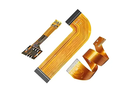
Flexible printed circuits carry one or more etched conductive layers on a dielectric film. They are common in smartphones, laptops, wearables, and automotive electronics. Flexible Copper Clad Laminate (FCCL) is the substrate, and it pairs a polyimide (PI) base film with copper foil. Therefore, hole quality controls whether the whole circuit works.
What Carbon-Coated Film for FCCL Copper Plating Does
Carbon-coated film is a critical step in via metallization of flexible copper-clad laminates. It deposits a dense layer of conductive graphite particles onto the dielectric walls of the via. As a result, layers connect electrically and the later copper plating proceeds smoothly.
Nano Graphite and Via Wall Coverage
Since the 1980s, carbon-coated film technology has been used in copper-clad laminate production. Process variation directly affects hole quality, so evaluation matters for early defect detection. For example, graphite particle sizes have dropped to the hundred-nanometer range for denser films. Also, the adsorbed graphite layer on hole walls is only tens of nanometers thick. Therefore, nanoscale adhesion is extremely hard to observe quickly and directly.
A Practical Evaluation Method and Validation Strategy
The work uses the most common PI-insulated flexible copper-clad laminate as the substrate. It applies qualitative and quantitative analysis to film surface and hole wall morphology, contact angles, and electrical resistance. Next, copper plating tests validate the results. In short, the aim is a simple and effective way to judge carbon-coated film performance.
Polyimide-Based FCCL Evaluation Steps
A polyimide-based FCCL evaluation follows a fixed order. First, cut PI films to 100 mm × 100 mm and run the carbon coating process steps. Next, inspect the film surface and the via walls. After that, measure contact angle and electrical resistance. Finally, confirm the film through copper plating tests.
Experiments: Materials and Instruments

Primary Materials
The study used FRS 522 # SW polyimide film from Tokuyama Corporation, Japan. It also used 2FPDR2003JC flexible copper-clad laminate from Tai Hong Technology Co., Ltd. The carbon coating process solution came from Medeme Technology Co., Ltd.
Testing Instruments
The instrument set included a Sigma500 scanning electron microscope (SEM) from Carl Zeiss, Germany. A Dimension XR Atomic Force Microscope (AFM) came from Bruker Corporation, Germany. The SL200K CN contact angle tester came from Shanghai Solon Information Technology Co., Ltd. A P15V-M(T) plasma treatment system came from Zhuhai Baofengtang Electronics Technology Co., Ltd.
Sample Preparation and Testing Methods
PI films were cut into 100 mm × 100 mm pieces and put through the carbon coating process steps. The samples were then readied for the surface and hole wall inspections described above. This keeps preparation consistent across every test batch.
Results and Analysis


The analysis reads four signals together. First, SEM images show film surface and hole wall morphology. Second, AFM data describe surface topography. Third, contact angle reflects the wettability of the treated surface. Fourth, electrical resistance indicates conductivity across the via.
However, the graphite layer is only tens of nanometers thick, so direct visual checks rarely suffice. Therefore, the method pairs qualitative images with quantitative numbers. Copper plating tests then confirm whether the carbon film supports reliable plating.
Conclusion
A Carbon-Coated Film Evaluation gives an early read on via quality before copper plating. It combines morphology, contact angle, and resistance checks with a plating test. Also, it relies on common PI-based FCCL material, so the method fits routine production. As a result, defects surface early and resource waste drops.
FAQ
What is a Carbon-Coated Film Evaluation?
A Carbon-Coated Film Evaluation is a check of the conductive graphite layer on via walls in flexible copper-clad laminate. It reviews film surface and hole wall morphology, contact angle, and electrical resistance, then confirms the result with copper plating tests.
Why is carbon-coated film for FCCL copper plating so thin?
Graphite particles are now mostly in the hundred-nanometer range, and the adsorbed layer on hole walls is only tens of nanometers thick. Therefore, the coating is hard to see directly, so instrument-based inspection is needed.
Which materials and instruments support a polyimide-based FCCL evaluation?
Typical materials include FRS 522 # SW polyimide film and 2FPDR2003JC flexible copper-clad laminate. Common instruments include SEM, AFM, a contact angle tester, and a plasma treatment system.
Related Posts
- PET vs FPC Selection — Related article
- PI Protective Film Process for Rigid-Flex PCBs: Reducing Flexible-Area Cosmetic Defects – GekunFlex — Related article
- Rigid-Flex PCB Air-Gap Design Yield Optimization – Part II — Related article
- Research on the process of PI protective film for R-FPCB – GekunFlex — Related article
- Rigid Flex PCB Manufacturing: A Process Overview – GekunFlex — Related article