FPC Routing: Design Rules, Cutting Methods, and Manufacturing Support
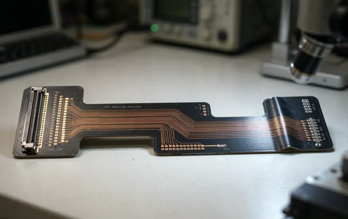
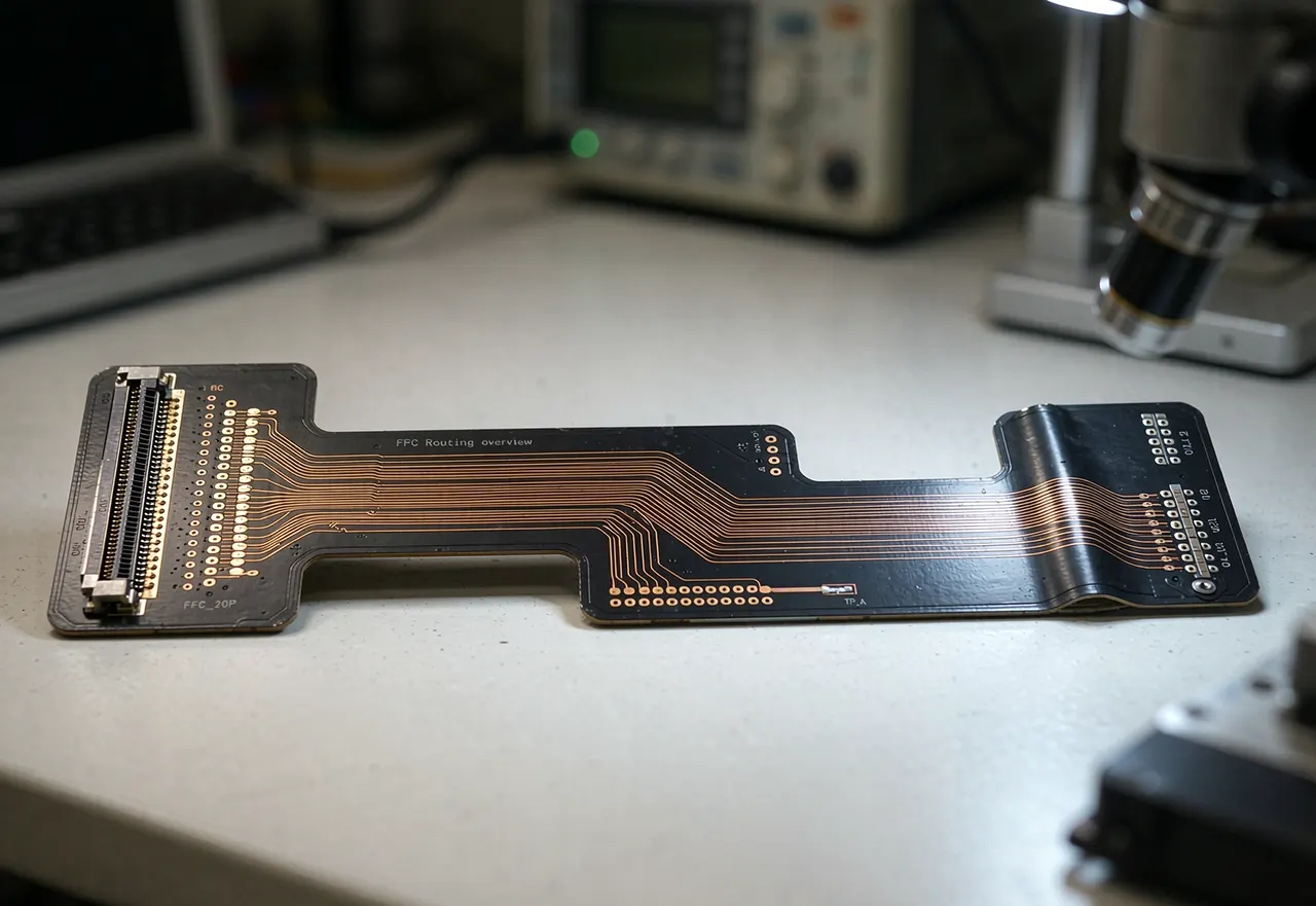
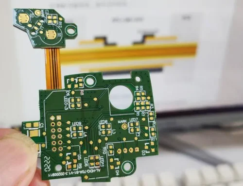
FPC routing has two meanings in flexible circuit manufacturing. In design, it means laying out conductors across a Flexible Circuit. In production, it means cutting finished parts out of the panel with a laser, CNC, or die tooling. Both steps decide bend life, fit, and unit cost.
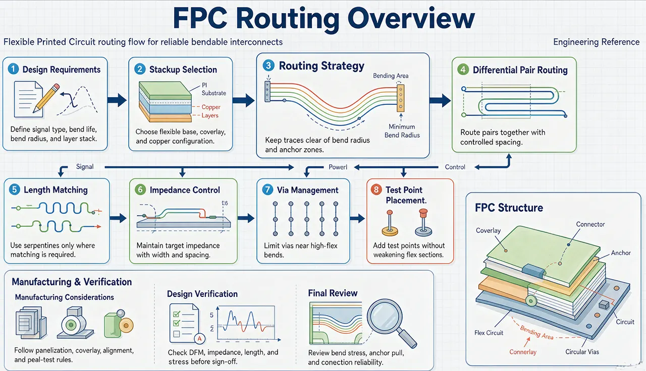
FPC RoutingOverview
What FPC Routing Means in Practice
FPC routing covers two connected workflows. First, engineers route copper traces along the flex body so signals survive bending and vibration. Second, the fabricator routes the panel profile to release each finished circuit from its carrier.
Therefore, a complete routing plan combines a CAD layout with a manufacturing method. Design rules control reliability, while the cutting method controls tolerance, tooling cost, and lead time.
Design Rules for Routing Conductors
Designers routing flexible circuit boards follow a few rules that protect against cracked traces. The list below covers the ones that matter most.
- Cross the bend at 90 degrees. Route traces perpendicular to the bend line, never parallel to it.
- Use arcs instead of right angles. Smooth curves spread stress over a longer path.
- Keep copper near the neutral axis. A thin, symmetric stack-up places conductors between the top and bottom coverlay.
- Widen traces inside the bend. A wider trace carries the same current with lower strain.
- Add teardrops and fillets. These soften the pad-to-trace transition and reduce stress points.
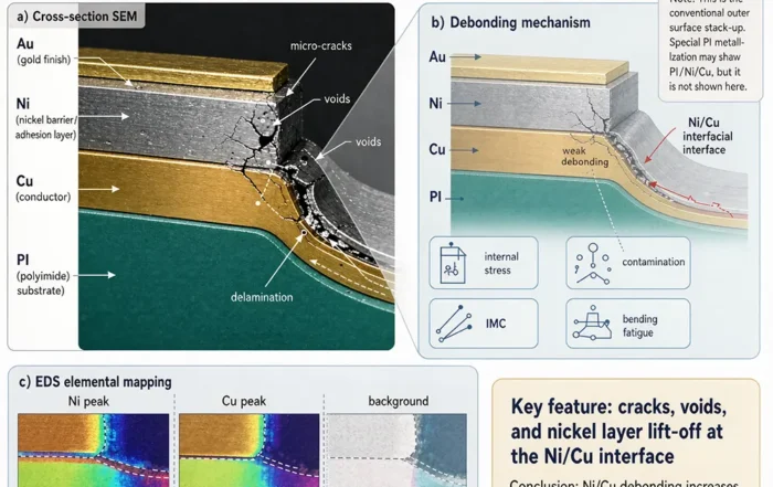
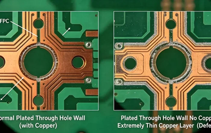
- Move vias out of the bend zone. Plated through-holes are rigid points that crack first.
- Use hatched ground planes. Solid copper stiffens the flex and lowers flexibility.
IPC-2223, the sectional design standard for flexible printed boards, gives detailed bend-radius guidance. As a rule of thumb, a static bend often works with a radius near 10 times the total stack thickness. Dynamic flexing needs far more, sometimes 20 to 100 times, depending on copper type and cycle count. Always confirm the final number with your fabricator.
Panel Routing Methods: Laser, CNC, and Die Cutting

After the layout is fixed, the next choice is how to cut the outline. Flexible panels are thin and floppy, so most shops hold them on a carrier frame until routing is finished. The table below compares the common methods.
| Method | How it works | Best for | Tooling |
|---|---|---|---|
| Laser routing | A focused beam cuts polyimide and adhesive | Fine outlines, prototypes, low to mid volume | Program only |
| CNC routing | A carbide bit mills the profile along a path | Complex contours, tabs, mid volume | Program plus fixture |
| Die cutting | A hardened steel die punches the outline | High volume, simple outlines | Steel die |
| Tab routing | Perforated tabs hold parts in the panel | Hand or fixture depaneling | Depends on cut method |
Typical routing tolerances sit near plus or minus 0.05 mm for laser, 0.10 mm for die cutting, and 0.10 to 0.15 mm for CNC. Treat these as starting points, not promises. Material thickness, copper weight, stiffeners, and panel size all shift the achievable window.
Data and Documentation to Prepare
Good routing starts with clean data. Therefore, send the following with your request:
- Outline as DXF or a Gerber profile layer
- Stack-up and material type, including adhesive and coverlay
- Bend lines, and whether the bend is static or dynamic
- Tab locations, widths, and keep-outs
- Stiffener and component areas
- Surface finish, impedance targets, and order quantity
Also confirm whether parts ship in panel form or depaneled. That single choice changes packaging, testing, and freight.
How Routing Choices Affect Cost and Lead Time
Laser routing needs no hard tooling. As a result, it suits prototypes and low volume, but cost per part stays higher. Die cutting flips that equation. The steel die adds upfront cost, yet unit price drops sharply once volume grows. CNC sits between the two and handles contours that a simple die cannot.
Tab count and tab width also matter. More tabs hold parts safely during plating and assembly, but they add depaneling labor later. For example, a narrow tab may need hand trimming, while a perforated tab snaps cleanly in a fixture.
Quality Checks After FPC Routing
Every routed panel should pass both mechanical and electrical checks. For instance:
1. Visual and AOI inspection for burrs, nicks, and exposed copper along the routed edge.
2. Dimensional check of the outline against the drawing tolerance.
3. Electrical test by flying probe or dedicated fixture.
4. Bend and flex testing where the application demands it.
5. Final packing in trays or tape for automated assembly.
IPC-6013 defines qualification and performance requirements for flexible printed boards. Therefore, ask your supplier whether the build targets Class 2 or Class 3.
Where FPC Routing Appears
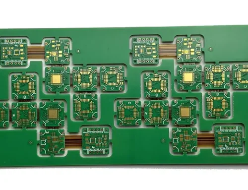
Routed flex appears in medical catheters, wearable sensors, camera modules, battery monitoring harnesses, and aerospace avionics. In addition, many designs mix flex with rigid sections. In those cases, routing rules apply to the flexible zone, while standard rigid rules cover the boards. Explore the Rigid-Flex PCB page for that hybrid approach, and review Our Markets to see the industries we serve.
Working With Gekun on FPC Routing
Gekun supports routing from design review through volume production. Our engineers check bend geometry, panel layout, and tab strategy before release. Then we match the cut method to your volume, tolerance, and budget.
Start with our Strengths to review capabilities, or open Contact Us to send drawings for a quote. The FAQS page answers common questions about materials, testing, and lead times. You can also read more technical notes on our Blog.
FAQ: FPC Routing
What is FPC routing?
FPC routing is the process of laying out conductors on a flexible printed circuit and then cutting the finished outline from the production panel. The design side controls electrical and mechanical reliability. The production side controls dimensional accuracy, tooling cost, and lead time.
What is the minimum bend radius for routed traces?
Common industry guidance suggests a radius near 10 times the total stack thickness for a static bend. Dynamic applications may need 20 to 100 times, depending on copper type and flex cycle count. IPC-2223 provides the formal design basis, so confirm the final value with your fabricator.
Which routing method should I choose?
Choose laser routing for prototypes and fine outlines, CNC routing for complex contours and mid volume, and die cutting for high volume with simple outlines. Tab routing works with any of the three when parts must stay in panel form for assembly.
What files do you need for an FPC routing quote?
Send a Gerber or DXF outline, the stack-up with material and coverlay, bend lines, tab data, keep-outs, surface finish, and quantity. Also state whether you want parts in panel or depaneled form, because that affects testing and packaging.
Can FPC routing be combined with rigid boards?
Yes. In a rigid-flex design, routing rules apply to the flexible zone while rigid board rules cover the stiff sections. The transition area needs extra care, since the copper and coverlay must survive repeated bending there.
Related Posts
- AI-Driven Optimization of FPCB Production Processes — Related article
- Rigid-Flex PCB Design Guide — Related article
- Pattern-Based FPC Routing Algorithm — Related article
- Pattern-Based FPC Routing Algorithm — Related article
- Flex Sensors Explained: Bend Detection — Related article