Flex PCB materials: their basic characteristics
Introduction
Flex PCB materials are essential in supporting a variety of design and operational objectives, including static or dynamic bending, compatibility with standard assembly processes, simplicity in manufacturing, and high production yield. Although flexible PCB materials may initially seem specialized, a relatively small set of materials is widely used to mass-produce flexible and rigid-flex PCBs. In this guide, we will explore the fundamental characteristics of flexible PCB materials and how they are utilized to construct flexible and rigid-flex PCBs.
Substrates and Coverlays
The most common substrate in rigid printed circuit boards (PCBs) is woven fiberglass impregnated with epoxy resin. Despite being classified as “rigid,” these materials exhibit reasonable flexibility when individual laminate layers are removed. The cured epoxy resin gives the circuit board its stiffness, and due to its use of epoxy, these boards are often referred to as organic rigid PCBs. While this may suffice for many applications, it lacks the flexibility needed for components subjected to continuous movement.
For flexible PCBs, polyimide (PI) is the most widely used substrate material due to its exceptional flexibility and high thermal resistance. Polyimide can endure the rigors of product assembly and multiple solder reflow cycles, making it stable under temperature fluctuations that cause expansion and contraction. Polyester (PET) is another common flexible circuit material but is unsuitable for high-temperature environments required during soldering. PET is typically used in low-cost electronics where the flexible portion includes printed conductors, with no lamination or soldering involved. However, for rigid-flex designs, polyimide remains the preferred choice due to its durability and thermal performance.

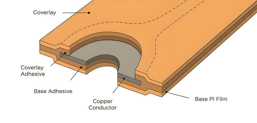
PI and PET films, along with thin flexible epoxy and fiberglass inner cores, form the common substrates for flexible circuits. These circuits are often protected by additional films (usually PI or PET, and occasionally flexible solder masks) that serve as overlays. Coverlays insulate the external surface conductors and prevent corrosion and damage, similar to the role of a solder mask on rigid PCBs. The thickness of PI and PET films ranges from ⅓ mil to 3 mils, with 1 or 2 mils being typical. In contrast, fiberglass and epoxy substrates are generally thicker, ranging from 2 mils to 4 mils.
Conductors
While low-cost electronics may utilize printed conductors—often made from carbon-based or silver-based inks—copper remains the most common conductor choice for flexible PCBs. Depending on the application, different forms of copper may be necessary. For simple flexible circuit sections designed to reduce manufacturing time and costs by eliminating cables and connectors, laminated copper foil (either electrolytic or ED) typically used in rigid PCBs is suitable. This is also true for applications requiring heavier copper weights to maintain narrow conductor widths, such as in planar inductors.
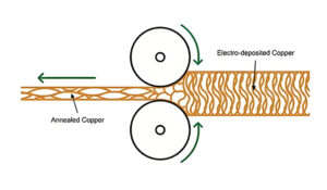
However, copper is susceptible to work hardening and fatigue. For applications involving repeated flexing or movement of the flexible circuit, a higher-grade rolled annealed (RA) foil is preferred. Although the additional annealing process significantly increases costs, annealed copper can stretch further before fatigue cracks occur and is more resilient to Z-axis bending—ideal for flexible circuits designed for continuous bending or rolling. The rolling and annealing process elongates the grain structure in the plane direction, enhancing the copper’s flexibility and resilience.
Adhesives
Traditionally, adhesives have been used to bond copper foil to PI (or other) films because, unlike typical FR-4 rigid circuit boards, annealed copper lacks the “tooth” necessary for reliable bonding through heat and pressure alone. Manufacturers supply pre-laminated, single-sided, and double-sided copper-clad films with adhesives typically made from acrylic or epoxy resin in thicknesses of ½ to 1 mil. These adhesives are specifically designed for flexibility.
However, “adhesiveless” laminates are becoming increasingly common due to new processes that involve direct plating or depositing copper on PI films. These films are preferred for high-density interconnect (HDI) circuits where finer spacing and smaller vias are required. Additionally, silicones, hot-melt adhesives, and epoxies are used when adding protective beads to flexible-to-rigid joints or interfaces, reinforcing the mechanical connection at the pivot points of these joints, and preventing rapid fatigue, cracking, or tearing during repeated use.
Single-Layer Flexible Circuits
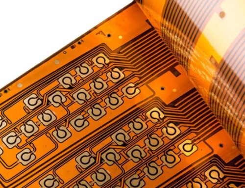
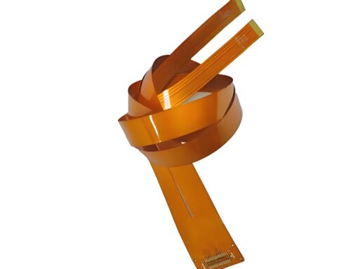
A typical single-layer flexible circuit is structured similarly to the most common finished FFC (flexible flat connector) cables, an alternative to rigid-flex PCBs where FFC connectors are used, and cost is the main driving factor. In a single-layer flexible circuit, copper is pre-laminated onto PI film by the material supplier, after which the copper is etched and drilled using a rigid backplate. Finally, an adhesive-based polyimide coverlay, pre-punched to expose the copper pads, is laminated. Any adhesive that may extrude during this process can be managed by expanding the exposed pad area.
Importance of Understanding Flexible PCB Materials
Understanding the materials used in flexible and rigid-flex circuits is crucial. Although manufacturers typically select materials to ensure high yield, it is essential to be aware of factors that may cause flexible PCBs to fail in the field. Knowledge of material properties also aids in the mechanical design, evaluation, and testing of the product. For instance, in automotive products, factors like heat, moisture, chemicals, shock, and vibration require precise material property modeling to determine product reliability and the minimum allowable bend radius. Ironically, the demanding environments that drive the need for flexible and rigid-flex PCBs often involve harsh conditions. Even low-cost consumer electronics are subject to significant wear from vibrations, drops, and exposure to sweat, among other factors.
When manufacturing circuit boards, each board section needs to be clearly illustrated in the manufacturing drawings, detailing the layer arrangement and materials used.
Conclusion
In summary, the careful selection of materials for flexible and rigid-flex PCBs is paramount to ensuring the reliability and performance of these circuits in various applications. By understanding the characteristics of substrates, conductors, adhesives, and overlays, engineers can design flexible circuits that meet the rigorous demands of modern electronics, particularly in challenging environments.



Leave A Comment