Rigid-Flex PCB Design Guidelines: Unlocking Efficiency and Innovation
Introduction
In the rapidly evolving world of electronics, the demand for more efficient, compact, and reliable devices has led to the rise of Rigid-flex PCBs (Printed Circuit Boards). Combining the best attributes of rigid and flexible PCBs, Rigid-flex PCBs Design Guidelines: offer unparalleled design versatility, improved performance, and greater durability. This article will delve into the essential design guidelines for rigid-flex PCBs, ensuring you maximize their potential while adhering to best practices. Whether you’re a seasoned designer or new to the field, these insights will guide you through creating robust and efficient rigid-flex PCBs.
Understanding Rigid-Flex PCBs
Definition and Benefits
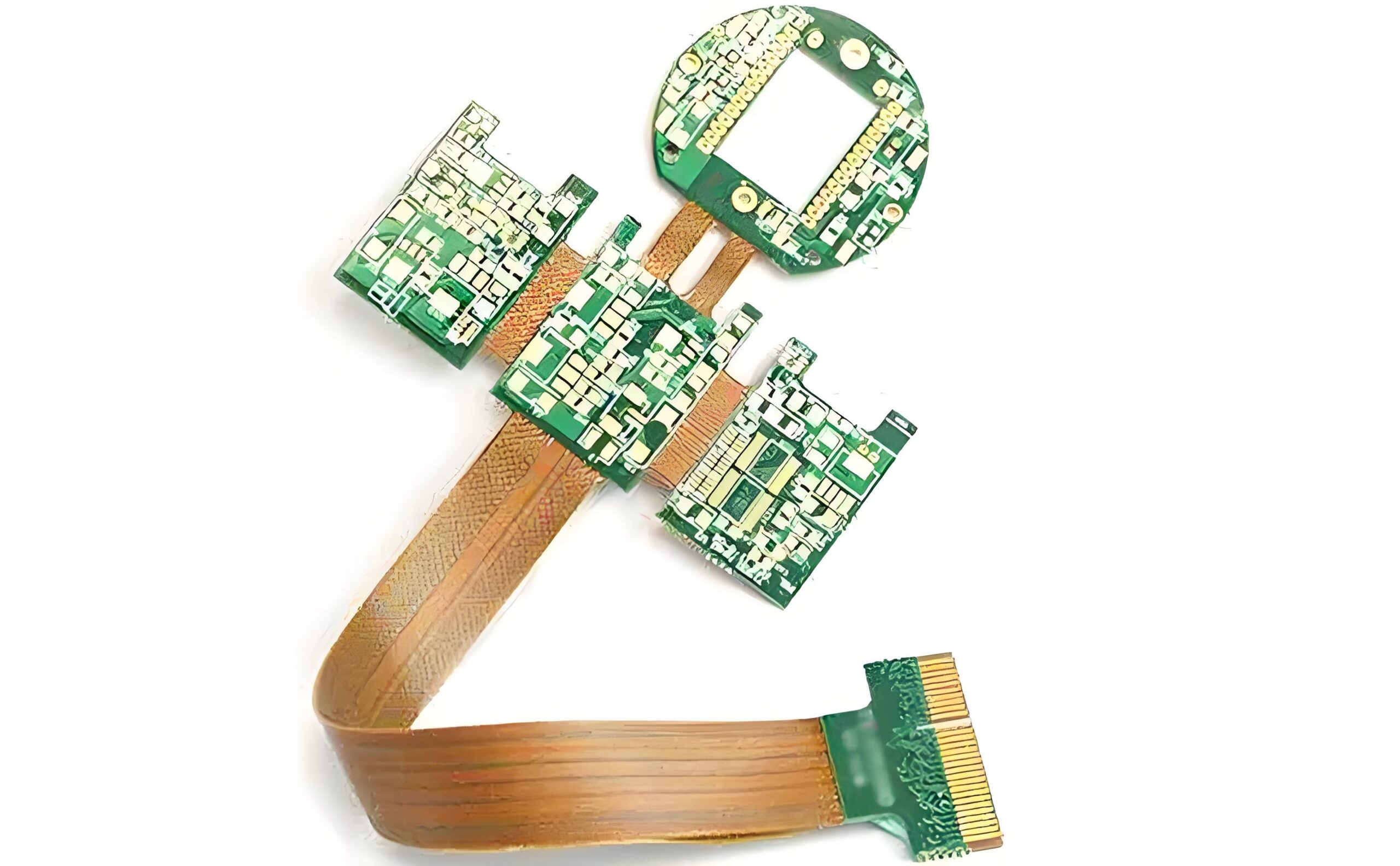
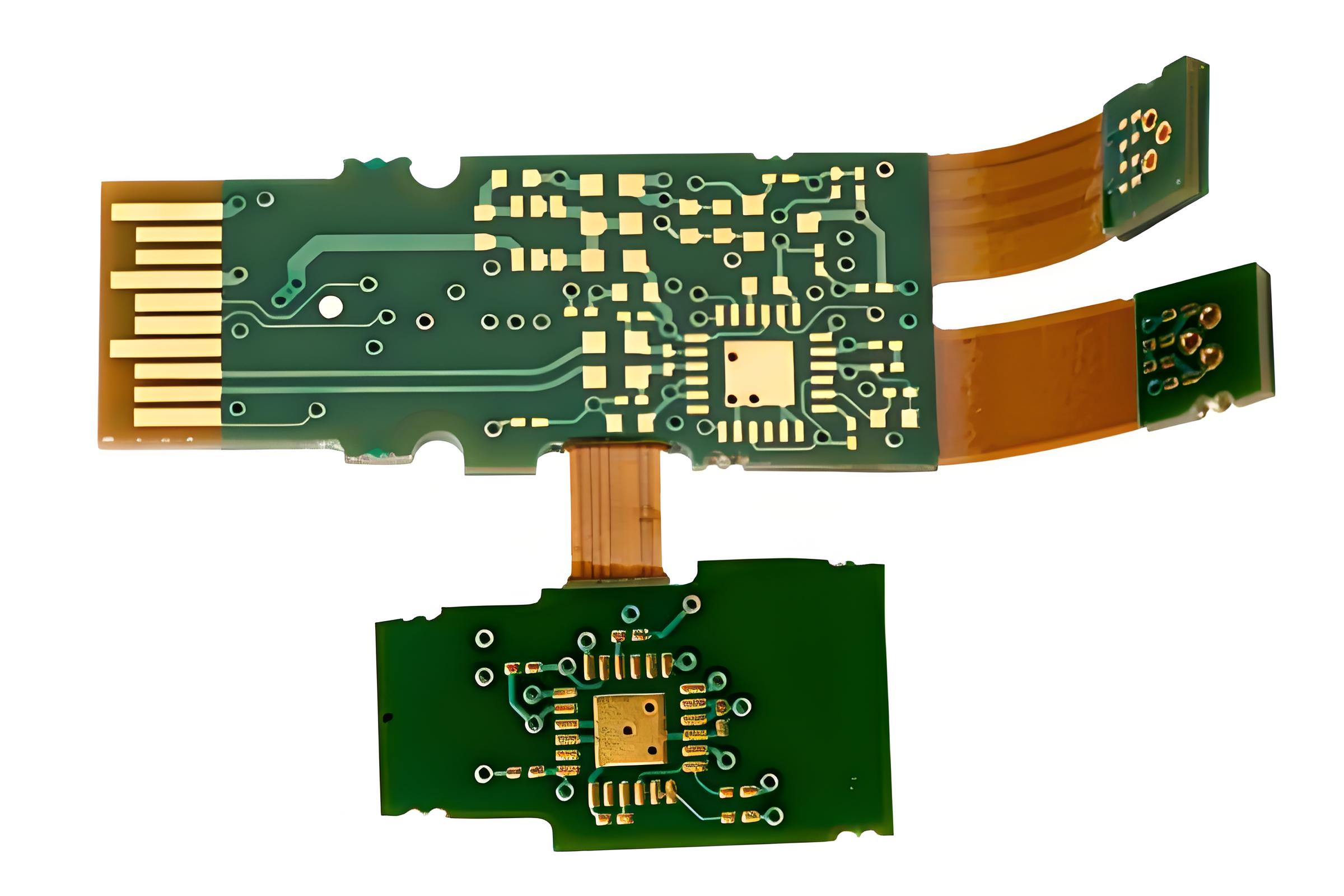
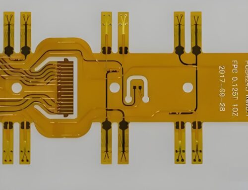
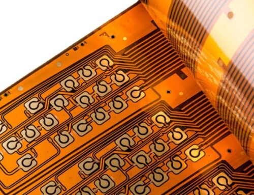
Rigid-flex PCBs are hybrid circuit boards that combine rigid and flexible substrates into a single integrated unit. This design offers numerous advantages, including enhanced mechanical stability, improved reliability, and greater design flexibility. The ability to fold or bend the flexible sections allows for more compact device designs, making rigid-flex PCBs ideal for applications where space and weight are critical factors.
Applications in Modern Electronics
Rigid-flex PCBs are used in a wide range of industries, including aerospace, medical devices, consumer electronics, and automotive systems. Their ability to withstand harsh environments and mechanical stress makes them a preferred choice for high-reliability applications. For instance, they are commonly found in smartphones, wearable devices, medical implants, and military equipment.
Design Considerations for Rigid-Flex PCBs
Material Selection
Choosing the right materials is crucial for the performance and durability of rigid-flex PCBs. The materials used for the rigid and flexible sections must be compatible and meet the specific requirements of the application. Typically, the rigid sections use FR4 or similar materials, while the flexible sections use polyimide due to its excellent thermal and mechanical properties. It’s essential to consider factors such as thermal expansion, dielectric properties, and moisture absorption when selecting materials.
Layer Stack-Up
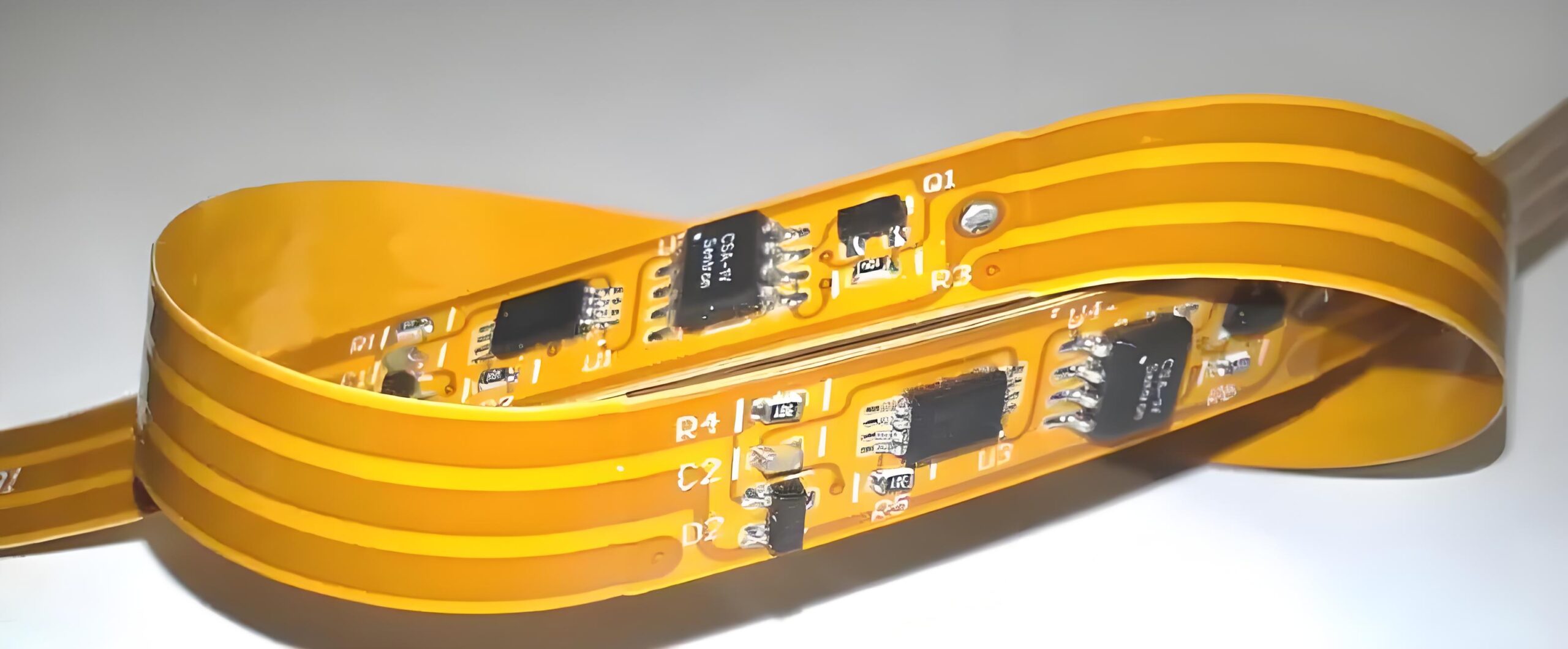
The layer stack-up in rigid-flex PCBs is more complex than in traditional PCBs. A well-designed stack-up ensures mechanical integrity and electrical performance. The flexible layers, typically made of polyimide, are sandwiched between the rigid layers. The number of layers and their arrangement should be optimized based on the design requirements. Proper stack-up design helps in minimizing stress on the flexible sections and ensures reliable performance.
Mechanical Design Guidelines
Bend Radius and Flexibility
One of the critical aspects of rigid-flex PCB design is managing the bend radius. The bend radius determines the flexibility of the PCB and affects the longevity of the flexible sections. A smaller bend radius can lead to increased stress and potential failure. As a general rule, the bend radius should be at least ten times the thickness of the flexible layer. Additionally, it’s advisable to avoid sharp bends and opt for smooth curves to distribute stress evenly.
Component Placement and Routing
Component placement and routing are crucial for the mechanical stability and performance of rigid-flex PCBs. Components should be placed on the rigid sections to avoid stress during bending. Routing traces through the flexible sections should follow straight paths and avoid sharp angles. It’s also important to consider the weight distribution and avoid placing heavy components near the bend areas.
Electrical Design Guidelines
Signal Integrity
Maintaining signal integrity is vital in rigid-flex PCB design. Signal traces should be routed with care to minimize noise and interference. Differential pair routing, controlled impedance, and proper grounding are essential techniques to ensure signal integrity. It’s also crucial to maintain consistent trace width and spacing, especially in the flexible sections, to prevent signal degradation.
Power Distribution
Efficient power distribution is another key aspect of rigid-flex PCB design. Power and ground planes should be well-defined and properly connected to ensure stable voltage levels throughout the PCB. Decoupling capacitors should be strategically placed near the power pins of components to filter out noise. Additionally, vias should be used judiciously to connect different layers and maintain low impedance paths.
Manufacturing and Assembly Tips
Panelization
Panelization is the process of grouping multiple PCBs on a single panel for efficient manufacturing. Rigid-flex PCBs require careful penalization to avoid damage during fabrication and assembly. The flexible sections should be supported adequately, and break-away tabs or rails should be used to secure the PCBs in place. Proper sanitization reduces handling stress and ensures consistent quality.
Soldering Techniques
Soldering rigid-flex PCBs can be challenging due to the thermal sensitivity of the flexible sections. It’s essential to use low-temperature soldering techniques and avoid prolonged exposure to heat. Reflow soldering is commonly used, but care must be taken to control the temperature profile. Manual soldering should be performed with precision to avoid damaging the flexible layers.
Testing and Validation
Reliability Testing
Reliability testing is crucial to ensure the performance and durability of rigid-flex PCBs. Environmental stress tests, such as thermal cycling, humidity exposure, and mechanical bending, should be conducted to evaluate the robustness of the design. These tests help identify potential failure points and allow for design improvements.
Quality Assurance
Quality assurance processes should be implemented throughout the manufacturing and assembly stages. Automated optical inspection (AOI), X-ray inspection, and electrical testing are essential to detect defects and ensure compliance with design specifications. A comprehensive quality assurance program helps in delivering reliable and high-performance rigid-flex PCBs.
Case Study: Gekun’s Innovative Rigid-Flex PCB Solutions
Industry Applications
Gekun, a leader in PCB manufacturing, has been at the forefront of developing innovative rigid-flex PCB solutions. Their products are used in various industries, including aerospace, medical devices, and consumer electronics. Gekun’s expertise in material selection, design optimization, and advanced manufacturing techniques has enabled them to deliver high-quality rigid-flex PCBs that meet stringent industry standards.
Success Stories
Gekun’s rigid-flex PCB solutions have been instrumental in the success of numerous projects. For example, their PCBs have been used in cutting-edge medical devices, providing reliable performance in critical applications. In the consumer electronics sector, Gekun’s PCBs have enabled the development of compact and lightweight devices with enhanced functionality. These success stories highlight the importance of adhering to design guidelines and leveraging advanced manufacturing capabilities.
Conclusion
Designing rigid-flex PCBs requires a thorough understanding of both mechanical and electrical principles. By following the guidelines outlined in this article, you can create robust and efficient rigid-flex PCBs that meet the demands of modern electronic applications. Incorporating best practices in material selection, layer stack-up, mechanical design, and electrical design will ensure the reliability and performance of your PCBs. Gekun’s innovative solutions and expertise in rigid-flex PCB manufacturing further demonstrate the potential of these advanced circuits in various industries.




Leave A Comment