Flexible Printed Circuits: Design & Manufacturing Guide
What Is a Flexible Printed Circuit (FPC)?
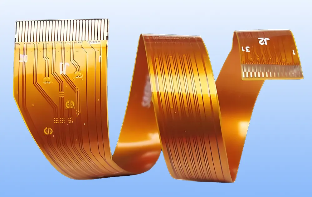
A flexible printed circuit (FPC) is a kind of electronic connector. They make it with flexible materials like polyimide. They layer these materials with conductive copper traces. The design allows for repeated bending, folding, or flexing while maintaining both mechanical and electrical performance.
Manufacturers create FPCs to replace traditional wiring harnesses or hardboards. People use them in places where being small, light, and strong against stress is important.
What Is the Use of FPC?
The primary uses of flexible printed circuits include:
- Space-Constrained Devices: Enabling compact designs in foldable smartphones, wearables, and IoT sensors.
- High-Density Wiring: Supporting complex circuits in medical imaging systems and aerospace avionics.
- Dynamic Applications: Withstanding repeated bending in robotics, flex circuit connectors, and automotive hinges.
- Signal Transmission: Ensuring reliable high-speed data transfer in multilayer flexible PCBs for 5G and AI devices.
What Is the Difference Between PCB and FPC?
| Feature | Rigid PCB | Flexible PCB (FPC) |
|---|---|---|
| Material | Rigid fiberglass (FR4) | Flexible polyimide or polyester |
| Bendability | Not bendable | Highly flexible, can bend repeatedly |
| Weight | Heavier | Ultra-lightweight |
| Applications | Static devices (e.g., motherboards) | Dynamic or compact systems (e.g., wearables) |
| Cost | Lower for high-volume production | Higher due to specialized materials/processes |
| Durability | Prone to cracking under stress | Resists vibrations and mechanical fatigue |
Composition and Materials of FPCs
Core Components
- Insulating Film: Polyimide (PI) or polyester (PET) forms the base layer, offering heat resistance and mechanical stability.
- Conductive Layer: Rolled copper foil ensures flexibility and conductivity.
- Adhesives: Bond layers or protective coatings, though adhesiveless designs improve thermal performance.
Specialized Materials
- Stiffeners: FR4, Aluminum, or stainless steel for structural support in rigid-flex designs.
- Coverlays: Protect circuits from moisture and abrasion.
Learn more in detail: Comprehensive Analysis of Flexible PCB Materials: Classification and Selection Guide
Types of Flexible Printed Circuit Boards
Single-Sided FPC: Basic electronic circuit for low-cost solutions.
Double-Sided FPC: Best value for money, most widely used.
Multilayer FPC: Supports high-density wiring in common applications like servers.
Other Types
Hollow boards, also known as window boards, serve applications that require open windows in the circuit.
Layered boards consist of two-sided circuits separated by insulation.
Rigid-Flex Boards: A combination of flexible and rigid board technologies.
FPC Manufacturing Processes

Double-sided Manufacturing process
These processes can be adjusted based on actual conditions.
Key Design Considerations
Bend Radius
- Single-layer: 3–6x conductor thickness.
- Multilayer: 10–15x conductor thickness.
- Dynamic applications (e.g., flex PCB cables): 20–40x conductor thickness.
Material Selection
- Use glue-free laminates for high flexibility.
- Rolled annealed copper for repeated bending.
Protection Methods for FPC
- Minimum Bend Radius: The smallest inner corner radius for flexible profiles should be 1.6 mm. Larger radii improve reliability and tear resistance.
- Cracks or Slots: Must end in round holes that are at least 1.5 mm wide. Nearby flexible circuit sections need this to move separately.
- Flexibility: Bend areas should have uniform widths, with variations in width and trace density minimized for better flexibility.
- Stiffeners: Use FR4 (common in rigid circuit boards) to reinforce high-stress areas
- Layering: In multilayer Flexible Printed Circuit designs, gap layering in areas subject to frequent bending is advisable. Thin PI materials can enhance flexibility and prevent cracking during repeated bends.
- Design the double-sided adhesive at the junction between gold fingers and connectors to prevent detachment during bending.
- Positioning: Positioning features should be on its own between the FPC and connectors to prevent misalignment during assembly.
- Rigid-Flex Hybrids: Optimizing rigid and flexible integration for IoT and robotics.
Challenges and Solutions
- High Initial Costs: Mitigated by partnering with flexible circuit board manufacturers offering low-volume prototyping.
- Fragility: Proper handling and strain relief in flex circuit connectors reduce damage risks.
- Ease of repair: Use ZIF (Zero Insertion Force) connectors for easy replacement.
Future Trends in FPC Technology
- High-Speed Flex Circuits: For 5G and AI-driven devices.
- Eco-Friendly Substrates: break down naturally occurring materials to reduce environmental impact.
- DIY Flexible PCB Kits: Enabling hobbyists and startups to prototype custom designs.
Conclusion
Flexible printed circuits redefine electronic circuit design by merging design flexibility with robust performance. From common applications in wearables to high-temperature automotive systems, FPCs excel where rigid circuit boards fall short. As industries demand smarter, lighter solutions, the synergy between rigid and flexible technologies will drive future innovations.


Leave A Comment