Rigid and Flexible PCBs: A Comprehensive Guide
Introduction
The advent and evolution of Flexible Printed Circuits (FPC) and Printed Circuit Boards (PCB) have given rise to a new product known as rigid-flex PCBs. These innovative boards combine the flexibility of FPCs with the robustness of PCBs through lamination and other processes, creating a unique hybrid that offers the best of both worlds. This article provides a detailed overview of rigid-flex PCBs, covering their classic structures, design guidelines, manufacturing processes, advantages and disadvantages, common applications, and solutions to production challenges.
Classic Structure of Rigid-Flex PCBs
LPI (Liquid Photoimageable) Layer:
LPI is a light-sensitive material that, after exposure, is developed to form the desired circuit patterns. It is typically coated on the outer surface of the base material and represents the outermost layer of the FPC structure.
Copper Foil:
Copper foil serves as the primary conductor material in the circuit. It is laminated beneath the LPI layer and etched to remove unwanted sections, leaving behind the necessary circuit patterns.
FR4 (Flame Retardant Grade 4):
FR4 is a rigid material used to enhance the rigidity and stability of the FPC. Positioned beneath the copper foil, it provides structural support.
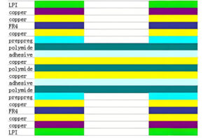
Prepreg (Pre-impregnated Material):
Prepreg is a semi-cured sheet material containing resin and fiber reinforcement. When heated, it bonds with the resin in adjacent layers to enhance mechanical strength and electrical performance.
Polyimide:
Polyimide is a high-temperature and chemical-resistant polymer material. Located below the prepreg layer, it acts as an insulating layer.
Adhesive:
The adhesive is used to bond materials between different layers. It is situated beneath the polyimide layer, aiding in layer adhesion.
Additional Copper Foil and Polyimide Layers:
Additional layers of copper foil and polyimide are used alternately to create the necessary conductive and insulating layers, culminating in a final structure with the required electrical and mechanical properties.
Pre-Production Preparation
Design Phase:
Electronic engineers design the circuitry and outline of the flexible-rigid board based on specific requirements.
CAM Processing:
The design is sent to the manufacturer, where CAM engineers process the design files.
Production Line Setup:
FPC and PCB production lines are set up to produce the necessary components.
Lamination:
Once the soft and hard boards are produced, they are laminated seamlessly according to the design specifications using a press machine.
Finalization:
The boards undergo a series of detailed processes to complete the rigid-flex PCB.
Design Specifications
Flexible Zone Circuit Design Requirements:
Avoid Sudden Changes in Width:
Lines should avoid abrupt widening or narrowing. Use teardrop shapes between different line widths to ensure smooth transitions.
Pad Design:
Pads should be maximized within electrical constraints, with smooth transitions rather than sharp angles. Independent pads should feature toe pads to provide additional support.
Dimension Stability:
Incorporate as much copper as possible in the design. Design solid copper foils in waste areas to enhance stability.
Cover Film Window Design:
a) Manual Alignment Holes:
Add manual alignment holes to improve alignment accuracy.
b) Window Design:
Consider the range of adhesive flow; typically, the window should be larger than the original design. Exact dimensions should be provided by manufacturing engineers (ME).
c) Small and Dense Windows:
Use specialized molds like rotary punches or die-cutting tools for small, dense windows.
Manufacturing Process
1. Drilling
2. Desmear
3. Chemical Copper Deposition
4. Copper Plating
5. Pattern Transfer
6. Etching and Stripping
7. Lamination
8. Surface Finish
9. Profiling
10. Cover Layer Design
11. Final Inspection and Packaging
12. Performance Testing
Quality control is critical at each stage, with stringent testing including visual inspections, dimensional checks, performance testing, environmental adaptability tests, and longevity assessments.
Advantages and Disadvantages
Advantages:
– Combines the flexibility of FPCs with the rigidity of PCBs.
– Ideal for products with specific requirements, helping to save internal space, reduce the overall product volume, and enhance performance.
Disadvantages:
– Complex production process.
– Higher production difficulty and lower yield, leading to higher costs and longer production cycles.
Common Applications
Industrial Use:
Rigid-flex PCBs are utilized in industries such as military, medical, and industrial sectors. These applications demand high reliability, precision, low impedance loss, complete signal transmission quality, and durability. The complex manufacturing process and low production volume contribute to the high unit cost.
Consumer Products:
In consumer electronics, rigid-flex PCBs are commonly found in foldable smartphones, camera modules, keyboards, and RF modules. They enhance performance by allowing three-dimensional connections between different PCBs and components, increasing usable PCB area and reducing signal transmission limits and assembly errors. Their lightweight and flexible nature significantly aids in reducing size and weight.
Challenges and Solutions in Rigid-Flex PCB Production
Technical Challenges and Solutions:
– Panel Shrinkage Control:
Use a “soft-first, hard-later” manufacturing sequence combined with pre-compensation and dehumidification to effectively manage material shrinkage.
– Plating and Surface Treatment:
Optimize plating parameters to ensure consistent copper thickness and adjust screen printing processes post-gold plating to prevent text peeling.
Reliability Verification:
Conduct rigorous testing such as 260°C reflow soldering three times, 288°C thermal shock, and 180-degree bending 100 times to confirm reliability under extreme conditions.
By systematically optimizing and innovating the manufacturing process for rigid-flex PCBs, key technical bottlenecks have been addressed, significantly enhancing product performance and market competitiveness, and injecting new vitality into this field.
Conclusion
Rigid-flex PCBs represent a significant advancement in PCB technology, combining flexibility and rigidity to meet the demands of modern electronic applications. While their production involves complex processes and challenges, the benefits they offer in terms of design flexibility and performance make them a valuable component in various high-tech industries. By understanding the classic structure, design guidelines, and manufacturing processes, and addressing the associated challenges, manufacturers can improve production efficiency and product quality, leading to continued innovation and growth in this field.



Leave A Comment