Rigid-flexible PCBs: design specifications and applications
Introduction
Rigid-flex PCBs, combining the technologies of rigid and flexible circuits, are critical components in the trend toward miniaturization and weight reduction in modern electronic devices. This paper gives a comprehensive overview of the design specifications and applications of rigid flexible PCBs. It aims to serve as a technical guide for design engineers, ensuring the efficiency and reliability of Rigid-Flex PCB designs.
What is a Rigid-Flex PCB?
According to IPC 6013 standards, flexible boards are classified into different types, including single-sided flexible boards, double-sided flexible boards, multilayer flexible boards, and Rigid-Flex PCBs. Under IPC 6013 Type 4, Rigid-Flex PCBs combine the advantages of both flexible and rigid boards. They can be described as hybrid boards or Rigid-Flex boards and are divided into two categories:
1. Flex-to-Install: This type can only be bent once during installation or maintenance.
2. Dynamic Flex: This type can be bent multiple times during usage.
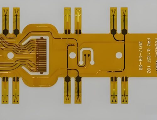
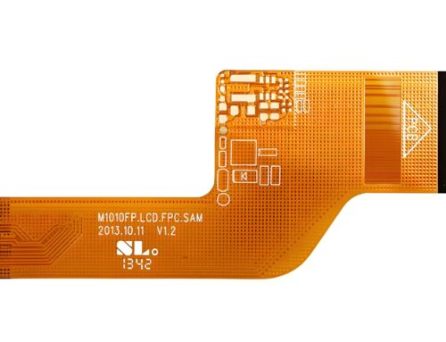
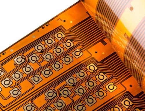
Rigid-flex PCBs are suitable for applications requiring compact sizes, where more components need to be integrated into a smaller area. Designed in 3D space, they offer higher space efficiency. Rigid-flex PCBs can be dynamically bent or folded, facilitating the formation of desired shapes during final product packaging. They require fewer interconnections, minimizing maintenance and enhancing reliability. Rigid-flex PCBs are commonly used in the medical, telecommunications, and aerospace industries.
Are Rigid-Flex PCBs Reliable?
Rigid-flex PCBs are highly reliable. Combining rigid and flexible boards forms a more three-dimensional and complete circuit board structure, effectively preventing issues such as poor insertion, thermal expansion, and contraction, thus enhancing durability and reliability. Traditional circuit boards, made from rigid materials, struggle with complex shapes, limiting design and wiring while posing a risk of short circuits. In contrast, the flexible regions in Rigid-Flex PCBs can freely bend, significantly reducing short-circuit risks and allowing for complex circuit board designs.
Key Considerations Before Designing
At the initial stage of designing a Rigid-Flex PCB, it is crucial to consider signal integrity, electrical performance, and mechanical adaptability. For applications involving high-speed signal transmission, designers should pay attention to impedance matching of signal lines, minimizing crosstalk and reflection, and controlling back drilling depth and precision to optimize signal quality.
Importance and Application of Back Drilling Technology
Back-drilling technology is vital for enhancing the signal integrity of Rigid-Flex PCBs. This technique precisely removes unused inner layer copper in multilayer boards to reduce parasitic capacitance and inductance in the signal path, thereby decreasing signal attenuation and distortion. The back drilling process requires precise depth control, typically within a tolerance range of ±0.05mm, ensuring stub removal without damaging necessary electrical connections. The back drill hole diameter is usually 0.2mm larger than the original through-hole to ensure complete copper removal.
Rigid-Flex PCB Design Details
– LPI (Liquid Photo-Imageable) Insulation Layer: Uses liquid photo-imaging materials on the circuit board to ensure high-precision circuit layout and excellent insulation performance.
– Via Design: The via design must balance signal transmission efficiency and mechanical strength, using techniques like blind vias, buried vias, and back drilling to meet the needs of different signal transmission layers.
– Material Selection: Choosing suitable substrates and prepreg materials, such as polyimide, ensures durability and reliability under repeated bending.
– Electrical and Mechanical Interfaces: In the transition area between rigid and flexible parts, design considerations must ensure smooth transitions, reduce stress concentration points, and maintain stable electrical connections and mechanical strength.

Key Performance Indicators
– Signal Transmission Quality: Ensuring fast signal transmission, low attenuation, and low crosstalk through reasonable layout and back drilling technology.
– Mechanical Performance: The flexible regions must withstand multiple bends without damage, while the rigid regions provide necessary structural support.
– Thermal Management: Considering heat dissipation design to ensure thermal stability under high-power operations.
– Reliability Testing: Including bend tests and Environmental Stress Screening (ESS) to verify long-term reliability.
Manufacturing and Production Considerations
– Design Rules: Adhering to strict design rules, such as minimum line width, spacing, hole diameter, and copper foil thickness.
– DRC (Design Rule Check): Performing design rule checks during the design phase to prevent potential manufacturing issues.
– DFM (Design for Manufacturing): Optimizing the design to fit manufacturing processes, considering equipment precision, material tolerances, and manufacturability.
Applications of Rigid-Flex PCBs
Rigid-flex PCBs are frequently seen in consumer electronics like digital cameras, portable camcorders, and MP3 players. They are also used in high-end aircraft-mounted weapon navigation systems. According to research, Rigid-Flex PCBs are most commonly used in manufacturing military aircraft and medical equipment. They offer significant benefits to military aircraft design by enhancing connection reliability while reducing weight. The benefits of reduced overall volume are also substantial. Implanted medical devices, like pacemakers and cochlear implants, benefit from the flexibility, folding capability, and reliability of Rigid-Flex PCBs. Imagine the scenario if a pacemaker stopped working due to a dislodged battery connection wire. With Rigid-Flex PCBs, the battery can be directly connected to the circuit layer and installed anywhere in the assembly.
Case Study: Applications of Rigid-Flex PCBs
Designers in various fields prefer Rigid-Flex PCBs because they often provide the only viable solution for specific product goals; typically, they start with a rigid prototype to test concepts and then transition to Rigid-Flex PCBs for the final product. A prime example of this approach is a project completed by Fluke Electronics in Plymouth, Minnesota.
Redesigning Military Infrared Imaging Technology
Technical Director Jeff Wisted was tasked with redesigning military infrared imaging technology. The infrared system was intended to be installed on micro aerial vehicles or unmanned aircraft, requiring the system to cover a handheld digital camera’s range within a 5-cubic-inch volume and a weight limit of 3 ounces. The challenge was to keep functionality and reliability while reducing space by 50% and weight by 95%.
The greatest challenge was to reduce the total weight from 3 pounds to less than 3 ounces. The only solution was to replace multiple interconnected rigid PCB components with a Rigid-Flex PCB. Although it was Jeff’s first experience using Rigid-Flex PCBs, every step was executed correctly.
Expert Opinion
Experts acknowledged, “Although Rigid-Flex PCBs are more expensive than traditional rigid boards, they provided the ideal solution for this project. We utilized flexible substrate interconnections rather than multiple PCB connectors, which was crucial in reducing space usage and weight, exactly what we needed.”
Due to their flexibility and foldability, Rigid-Flex PCBs can be used to create custom circuits that maximize the available space within a device. Jeff leveraged this feature to minimize the system’s overall footprint. Despite the higher production costs, the benefits outweighed the costs since the design was not intended for mass production.

Conclusion
Designing Rigid-Flex PCBs is complex, requiring a thorough understanding of electrical, mechanical, and material science. Adhering to strict design specifications and manufacturing standards is crucial for successful Rigid-Flex PCB design. By optimizing design processes and integrating advanced manufacturing technologies, we can develop high-performance, reliable Rigid-Flex PCBs to meet the growing demands of electronic devices.
The integration of Gekun’s advanced Rigid-Flex PCB technology ensures that the design and manufacturing process adhere to the highest standards, delivering exceptional performance and reliability for various applications.


Leave A Comment