How to Choose the Right Flex Material for Your PCB


In the fast-evolving world of electronics, flexible circuits enable revolutionary design possibilities. The foundation of any high-performance FPC lies in selecting the right flex material. But how do you choose the best option when there are so many combinations — RA or ED copper? Adhesive or adhesiveless? Thick or ultra-thin?
This article provides a professional yet clear guide tailored for engineers and sourcing managers, answering:
- What is flex material?
- What is flex base material?
- What is flex material made of?
- And ultimately, how to choose the right one for your project.
What Is Flex Material?
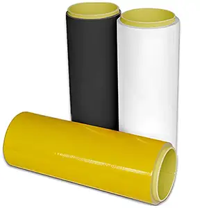
Coverlay Film
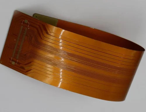
Flex material refers to the layered material system used to fabricate flexible printed circuit boards (FPCs). It must allow for repeated bending while maintaining:
- Dimensional and mechanical stability
- Good dielectric properties
- Thermal and chemical resistance
- Excellent adhesion and surface reliability
A standard flex material typically consists of:
| Layer | Description |
|---|---|
| Base Film | Insulating layer, usually Polyimide |
| Copper Foil | Conductive layer, either RA or ED copper |
| Adhesive (optional) | Binds copper to the base film |
| Coverlay or Protective Film | Provides insulation and mechanical protection |
What Is Flex Base Material?
The flex base material serves as the core dielectric layer, providing both mechanical support and electrical insulation. The most common base materials include:
| Base Material | Description | Typical Use Case |
|---|---|---|
| Polyimide (PI) | High thermal stability, excellent flexibility | Widely used in most FPCs |
| PET (Polyester) | Economical, low thermal endurance | Consumer electronics, static applications |
| LCP (Liquid Crystal Polymer) | Low Dk/Df, excellent for RF circuits | High-speed or RF flex PCBs |
What Is Flex Material Made Of?
To ensure optimal performance, each layer must be carefully selected:
| Component | Details |
|---|---|
| Base Film | Usually, polyimide (13–50µm) determines heat resistance and flexibility |
| Copper Foil | RA (rolled annealed) or ED (electrodeposited), varies by application |
| Adhesive | Polyacrylate or epoxy, used in adhesive-based systems |
| Coverlay | Polyimide with adhesive or photoimageable solder mask |
Tip: These materials work together to provide the right balance of bendability, reliability, and electrical performance.
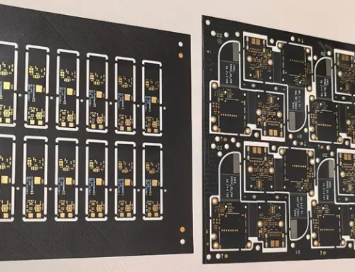
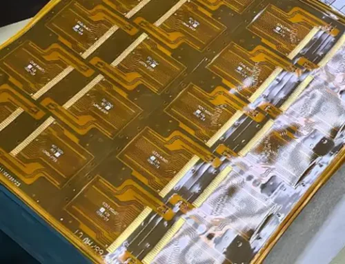
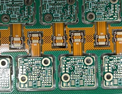
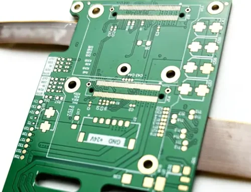
Flex PCB Material Types & Their Applications
| Type of FPC | Description | Material Characteristics |
|---|---|---|
| Single-Layer | Copper on one side of PI | For simple circuits (LEDs, antennas) |
| Double-Layer | Copper on both sides with PI core | More routing space, mid-complexity |
| Multi-Layer | Alternating PI and copper layers | Smartphones, military, aerospace |
| Rigid-Flex | Combines FR4 with PI flex zones | Wearables, compact embedded systems |
How to Choose the Circuit Board Materials
Selecting the right flex PCB material means evaluating mechanical flexibility, electrical needs, and environmental stress factors.
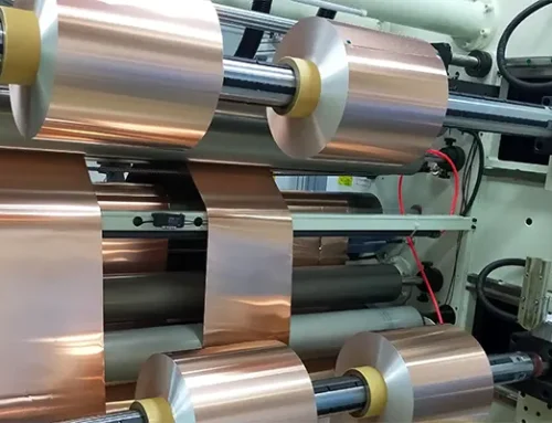
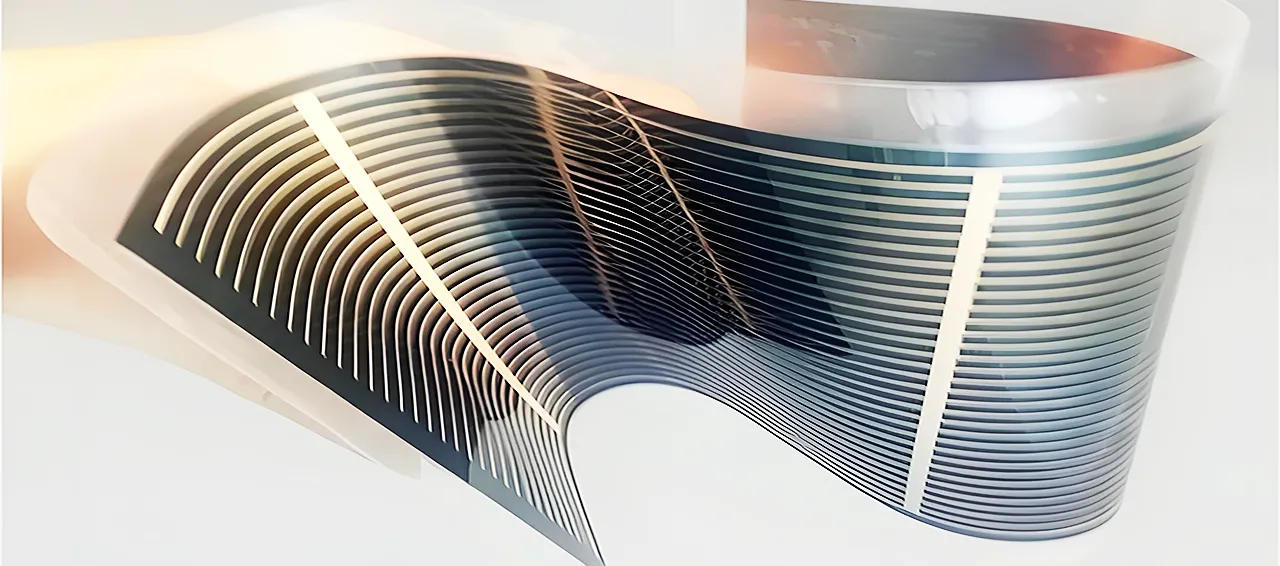
1. Copper Foil Type: RA vs. ED
The following figure shows the manufacturing process of RA Copper and ED Copper
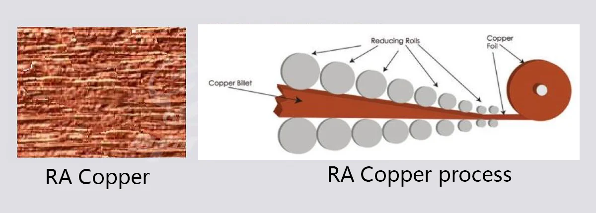
RA Copper
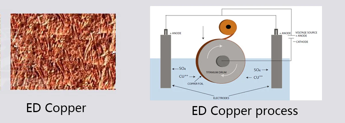
ED Copper
| Copper Type | Characteristics | When to Use |
|---|---|---|
| RA (Rolled Annealed) | High ductility, excellent for dynamic flex | Wearables, foldable displays |
| ED (Electrodeposited) | Lower cost, less flexible | Static or limited flexing applications |
Tip: RA is preferred in dynamic flex zones due to its grain structure.
2. Adhesive Structure: Adhesive vs. Adhesiveless
| Structure | Pros | Cons |
|---|---|---|
| Adhesive-based | Lower material cost, mature process | Reduced thermal stability, thicker |
| Adhesiveless | Better heat resistance, thinner stack | Slightly higher cost |
Tip: Adhesiveless is recommended for HDI designs and high-reliability circuits.
3. Copper Thickness
| Thickness | Use Case |
|---|---|
| 9µm–12µm | HDI circuits, fine-line etching |
| 18µm–35µm | General-purpose FPCs |
| 70µm+ | High-current or power circuits |
Tip: Too thick copper may reduce bendability. Thinner copper = better dynamic performance.
Practical Selection Examples
Conclusion
For further information, please refer to: Comprehensive Analysis of Flexible PCB Materials: Classification and Selection Guide.
Friendship link:


FAQ:
1. What is the flex base material, and why is it important?
The flex base material is the core dielectric film—typically polyimide (PI), PET, or LCP—responsible for providing electrical insulation and mechanical stability. It determines the flex circuit’s heat resistance, flexibility, and suitability for applications such as smartphones, wearables, sensors, and RF modules.
2. What materials make up a flexible PCB?
A flexible PCB is generally composed of:
Base Film: Polyimide (13–50 µm)
Copper Foil: RA (rolled annealed) or ED (electrodeposited)
Adhesive: Polyacrylate or epoxy in adhesive-based systems
Coverlay: Polyimide with adhesive or photoimageable mask
These layers work together to balance reliability, bend performance, and electrical characteristics.
3. How do I choose between RA copper and ED copper?
Choose RA copper for applications that require frequent bending, such as foldable devices and wearables, because it has high ductility.
Choose ED copper for static or low-flex designs such as sensors or simple consumer electronics, as it is more cost-effective but less flexible.
4. Should I use adhesive-based or adhesiveless flex material?
Use adhesive-based materials when cost and mature processing are priorities.
Use adhesiveless materials when you need better thermal resistance, thinner stack-ups, fine circuits (HDI), or higher reliability.
Adhesiveless PI is the preferred choice for high-performance or dynamic bending designs.
5. How do I select the right flex material for my application?
Consider three key factors:
Flexing requirement: Dynamic bend → RA copper; Static bend → ED copper
Thermal environment: High heat → Adhesiveless PI or LCP
Electrical performance: RF or high-speed → LCP base; HDI → thin copper (9–12 µm)
Example: Foldable phones use RA copper + adhesiveless PI, while static sensors typically use ED copper + adhesive PI.