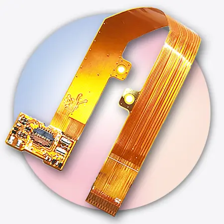
 A manufacturer creates a flexible circuit board using a flexible material. It can include printed wires and parts, and may or may not have a protective cover. Flex circuits have the unique ability to flex and move, unlike conventional stiff circuit boards. This makes them perfect for devices with little room to spare or that need parts to move during operation.
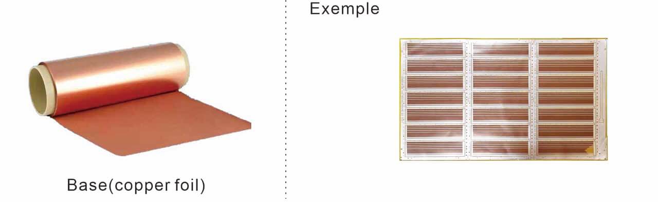
Flexible printed circuits use thin, lightweight parts and can bend or fold to fit the electronic device’s design. These substances serve as the foundation (or substrate) for copper wire.
Due to their flexible nature, such circuits can be bent, twisted, or folded without damaging them. That’s why flex circuits are perfect for small electronics and tight spaces where flexibility matters most.
Key benefits of flexible circuits include:
- Thin and lightweight: Ideal for use in small, portable, and wearable devices.
- Ultra high tensile strength: This braided Type-C charging cable is of Superior quality that can handle up to 20,000 bends.
- Space-saving: Fits anywhere, even in small or oddly-shaped bathrooms.
- Better signal quality: Lower EMI by de-embedding fewer interconnects.
What is the Difference Between a Flex Circuit and a Rigid PCB?
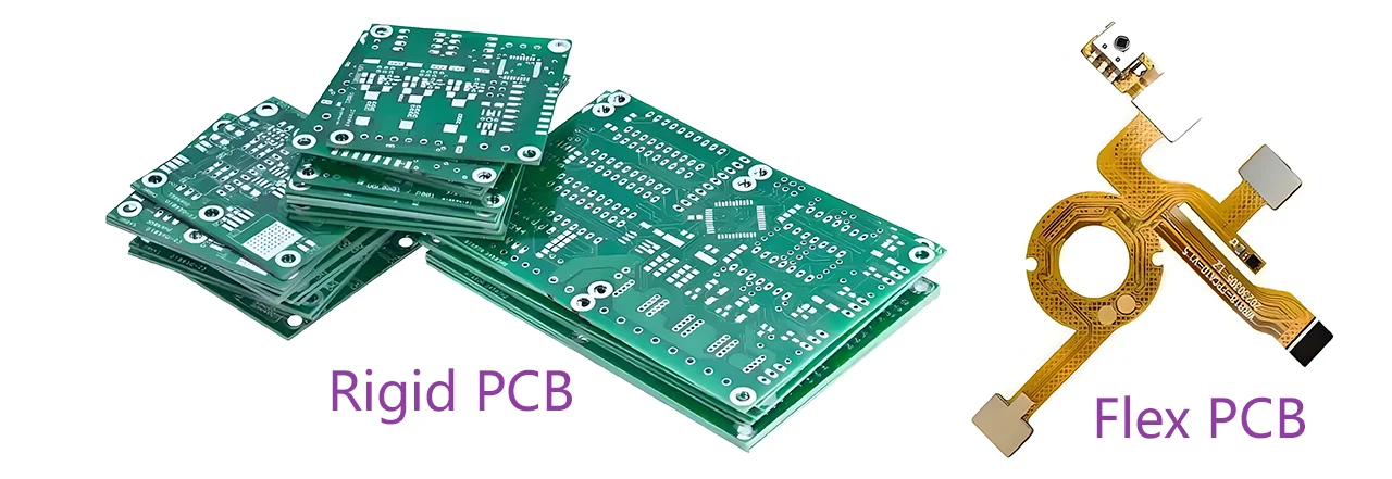
Rigid PCB and Flex PCB
Flexible circuits and rigid PCBs play different roles in electronics. Knowing the difference helps you choose the right one for your application. Below is a detailed comparison, Below is a detailed comparison:
| Substrate | Polyimide (PI) or PET film | FR-4 fiberglass |
| Bendability | High (dynamic or static flexing) | Rigid (no flexibility) |
| Weight | Lightweight | Heavy |
| Applications | Wearables, medical devices, and drones | Computers, servers, fixed electronics |
| Assembly | Fewer connectors, simplified wiring | Multiple interconnects required |
| Cost | Higher for complex designs | Lower for high-volume production |
Flex circuits are ideal for dynamic bending applications, like folding smartphones or robotic joints, where rigid PCBs would break.
Stiff PCBs, however, are ideal for stationary, high-power applications, such as motherboards or power supplies.
Other related post: Rigid PCB and Flexible PCB: Which Wins for Your Applications?
Flexible Circuit Technologies & Manufacturing Process

flexible circuit production process
- Preparation of Substrates: Correct selection and cleaning of the substrate (PI or PET) for adhesion.
- Circuit Imaging & Etching: This process transfers the circuit image onto copper-clad film using photolithography. Then, we etch away the extra copper.
- Drilling & Plated Through Holes (PTH): Creating vias and holes for layer interconnection, then plating them with conductive material.
- Coating Application: Laminating a protective insulating layer (coverlay) to shield the circuits from damage.
- Surface Treatment: Applying finishes like ENIG (Electroless Nickel Immersion Gold) or OSP (Organic Solderability Preservative) to enhance solderability.
- Final Testing: Conducting electrical tests and inspections to ensure functionality and durability.
Gekun is a flexible circuit technologies inc. At Gekun, we use advanced methods and strict quality checks. This helps us create high-performance flex circuits for medical devices, automotive systems, and consumer electronics.
Detail related post:
Types of Flexible Circuits We Manufacture
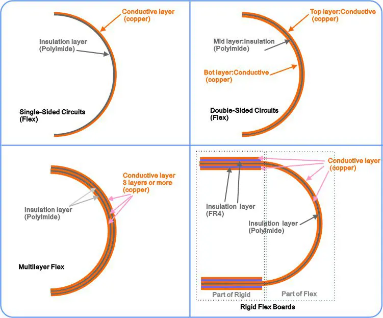
Simple introduction of flexible circuit board type
Gekun supports a broad range of custom and standard configurations:
· Single-Sided Circuits – Simple, cost-effective circuits
· Double-Sided Flex Circuits – More routing capability in compact form
· Multilayer Flex Designs – High-density solutions with EMI shielding
· Rigid Flex Boards – Ideal for 3D packaging and mechanical support
We offer quick-turn flex prototyping and dynamic flexing solutions tailored to custom requirements.
Why Choose Gekun Among Flexible Printed Circuit Manufacturers?
Gekun stands out among flexible circuit board manufacturers for its:
· Engineering expertise in flex circuit boards
· End-to-end solutions: from concept to flexible circuit board assembly
· Capabilities in high-density circuit designs
· Use of specialized circuit board materials
· Adherence to ISO, RoHS, and IPC standards
With global support and our own tools, we compete with established companies like Flexible Circuits Warrington. We offer quick service and new ideas.
Our Capabilities
| Product | Standard Flex Capabilities | Advanced Flex Capabilities | Rigid Flex Capabilities |
|---|---|---|---|
| Standard Panel Size | 9.85″ (250mm) x 15.75″(400mm) | 3.94″ (100mm) x 3.94″ (100mm) | 9.85″(250mm) x 15.75″(400mm) |
| Line Width and Spacing | 1/4 oz. Cu / .002″ (50μm) 1/3 oz. Cu / .002″ (50μm) 1/2 oz. Cu / . 003″ (76μm) 1 oz. Cu / .004″ (102μm) 2 oz. Cu / .005″ (127μm) | 1/4 oz. Cu / .002″ (25μm) 1/3 oz. Cu / . 002″ (35μm) 1/2 oz. Cu / .003″ (50μm) 1 oz. Cu / .004″ (76μm) 2 oz. Cu / .005″ (102μm) | 1/4 oz. Cu / .002″ (50μm) 1/3 oz. Cu / .002″ (50μm) 1/2 oz. Cu / .003″ (76μm) 1 oz. Cu / .004″ (102μm) 2 oz. Cu / .005″ (127μm) |
| Copper Thickness | 1/4 oz. Cu (9μm) to 2oz. Cu (71μm) | 1/4 oz. (9μm) to 1/2 oz. (18μm) | 1/4 oz. (9 μm) and higher |
| Layer Count | 10 | 2 typical, Max of 4 | 12 (To Date) |
| VIA /DRILL SIZE | |||
| Minimum Drim (Mechanical) Hole Diameter | 006″ (152μm) | 004″ (102μm) | 006″ (152μm) |
| Minimum Micro Via (Laser) size | .004″ (102μm) | .002″ (50μm) | .004″ (102μm) |
| SOLER MASK | |||
| Solder Mask Dam (Web) | .003″ (76μm) | .002″ (50μm) | .003″ (76μm) |
| Solder Mask Registration Tolerance | .003″ (76μm) | .001″ (25μm) | .003″ (76μm) |
| SHIELDING MATERIALS | Copper Silver Ink 7 Shielding film /Carbon | Copper Silver Ink 7 Shielding film /Carbon | Copper/ Silver Ink / Shielding film /Carbon |
| STIFFENER | |||
| Stiffener Material | Polyimide /FR4 / Metal | Polyimide /FR4 / Metal | FR4/ Polyimide |
| PI Stiffener | |||
| Stiffener Registration | .008″ (203μm) | .004″ (102μm) | .008″ (203μm) |
| FR4 Stiffener | |||
| Stiffener Registration | .006″ (152μm) | .004″ (102μm) | .006″ (152μm) |
| LEGEND | |||
| Minimum Height | .032″ (813μm) | .020″ (508μm) | .032″ (813μm) |
| Minimum Width | .006″ (152μm) | .003″ (81μm) | .006″ (152μm) |
| Registration | +/- .005″ (127μm) | +/- .005″ (127μm) | +/- .005″ (127μm) |
| IMPEDENCE | |||
| IMPEDENCE | +/- 10% | +/- 10% | +/- 10% |
| TOOLING | |||
| Hard Tooling Tolerance | .002″ (50μm) | .002″ (50μm) | .002″ (50μm) |
| Zif Tolerance (Hard Tool, CMD. or Laser) | .002″ (50μm) | .002″ (50μm) | .002″ (50μm) |
| CMD Tolerance (Chem Mill Die) | .004″ (102μm) | .004″ (102μm) | .004″ (102μm) |
In summary, if you have a flexible printed circuit, we can help.
Applications of Flex Circuits
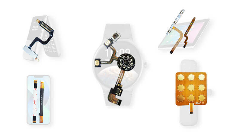
- Flexible PCBs are found across key industries:
- Medical: Catheters, wearable monitors, imaging tools
- Consumer Tech: Tablets, drones, cameras
- Automotive: EVs, dashboard controls, lighting systems
- Industrial: Sensors, motor controllers, automation systems
- Aerospace: Navigation modules, lightweight avionics
- Energy: Flexible circuit bonding for batteries
They effectively replace bulky wire harnesses, enabling streamlined design and easier assembly in tight enclosures.
Contact Us for Custom Flex Circuit Design
Need a flexible PCB board for your next project? Get in touch with Gekun for expert design and flexible circuit board manufacturing process support.
Materials Used in Flex Circuits
The performance of any flexible circuit depends on material choices:
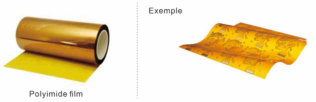
· Base Film: Polyimide PI or Polyester PET
· Copper Type: Rolled Annealed (RA) or Electro-Deposited (ED)
· Adhesives: Epoxy, acrylic compounds

· Insulating Layers: Coverlay film laminated with adhesive
· Reinforcement: FR4 stiffeners, stainless steel
We also utilize advanced film for flexible circuit fabrication to meet harsh environment needs and extend the lifecycle.
FAQs About Flexible Circuits
What is FPC in electronics?
A flexible printed circuit (FPC) is a bendable board used in electronics. It is made on a polyimide or PET base.
How to make a flex circuit?
Involves layering copper over film, patterning, applying insulating layers, forming vias, and conducting testing.
What is the difference between a flex circuit and a PCB?
Flex circuits are thin and flexible, while traditional PCBs are rigid and thick. The former is ideal for dynamically flexing applications.
Where are flexible PCBs used in electronic components?
You can find them in devices like smartphones, EV modules, and drones.
Are flexible circuits a cost-effective solution?
Yes, due to fewer interconnects and simpler enclosures.
Do you support single-layer or multilayer designs?
Yes, we offer both single-layer and multilayer flex depending on complexity.
Which circuit materials do people use?
We use PI film, copper foil, and adhesive systems to meet insulating material and conductivity requirements.
Are rigid flex circuits different?
Rigid flex combines flexible and rigid layers, often used in compact systems.
How do sided flex circuits benefit layout?
They allow optimized signal routing and compact form factors in single-sided or double-sided flex configurations.
What is the Difference Between PI Film and PET Film?
Polyimide (PI) and polyester (PET) are the two most common materials used in flexible circuits, each with unique properties:
- PI Film:
- High temperature resistance (up to 400°C), making it ideal for aerospace and automotive applications.
- Excellent chemical and mechanical stability, suitable for harsh environments.
- Higher cost compared to PET, but offers superior performance.
- PET Film:
- Lower cost, often used in consumer electronics like keyboards and touchscreens.
- Good flexibility and electrical insulation, but less durable under high heat.
- Limited to low-temperature applications (typically below 105°C).
Choosing between PI and PET depends on your project’s requirements, such as budget, environmental conditions, and performance needs.

Single Sided Flex
Double Sided Flex
Multilayer Flex PCB
Rigid Flex PCB
Gekun is a premier global supplier of design and production of Flexible printed circuit in China
Get A Quote


