Flexible PCB Design: Avoid These 6 Common Mistakes


Flexible PCB Design: Avoid These 6 Common Mistakes
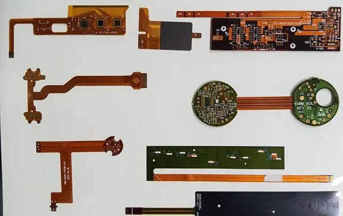
Flexible PCB design is crucial for creating lightweight, compact, and high-performance electronics. Flexible printed circuits (FPCs) have three main advantages over rigid circuit boards. They are lighter, more adaptable, and can bend without breaking. However, these benefits also come with specific design challenges that many engineers overlook.
This guide from Gekun, a leading PCB manufacturer, highlights six common mistakes to avoid when designing FPC boards. Each section includes practical advice, technical guidance, and design principles based on real-world engineering.
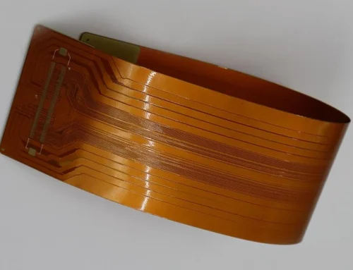
Ignoring Minimum Bend Radius
Issue: Designers new to flexible circuits often overlook how bend radius impacts reliability. Bending too much or making sharp curves can lead to cracks in the copper layer. It can also cause layers of dielectric materials to separate or traces to fail while in use.
Solutions:
- For static applications, maintain a bend radius of at least 6x the board thickness.
- For dynamic flexing, use 100x thickness, and adopt staggered trace layouts to reduce stress.
- Use polyimide-based materials (e.g., PI film) for better flexibility and thermal stability.
- Apply mechanical simulations (e.g., ANSYS) to validate against 100,000+ flex cycles.
- Reinforce critical zones with stiffeners like FR4 or stainless steel, especially near connectors.
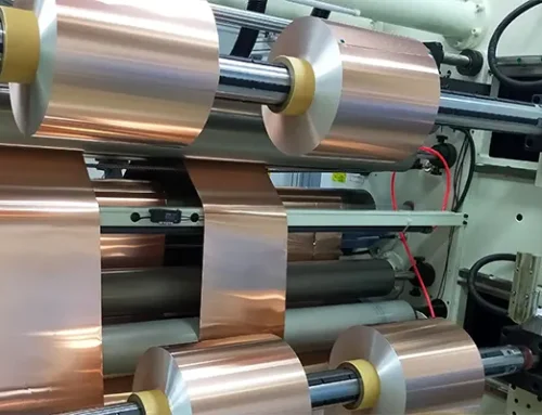
Poor Material Selection and Stackup Planning
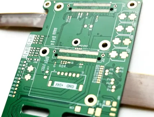
Issue: Improper selection of circuit board materials leads to signal loss, deformation under thermal stress, or delamination. This is especially true in rigid flex PCBs, where stackup asymmetry can trigger warping.
Solutions:
- Use polyimide substrates for high-temp resilience up to 260°C.
- Avoid PET in medical or high-temperature applications.
- Choose acrylic adhesives for dynamic flex zones; use epoxy in rigid areas.
- Balance layer structure to avoid curling in single-layer or multilayer flexible PCBs.
- Match copper thickness with controlled impedance needs.
- For EMI shielding, consider copper foil and copper plating strategies.
Insight: High-speed flex PCB design requires symmetry and compatibility with signal integrity standards.
Other References: Mechanical Durability of PI‑Based FPCs
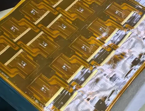
Overlooking Connector Compatibility
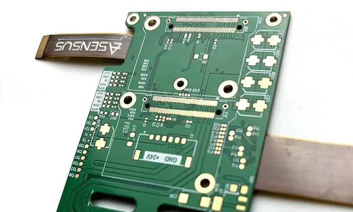
Issue: Misaligned or incompatible FPC connectors result in intermittent signals or mechanical failure. This is a frequent problem during prototyping or modular development.
Solutions:
- Ensure the connector pitch (0.3mm, 0.5mm) aligns with the trace spacing.
- Use ZIF or LIF connectors to reduce insertion pressure.
- Include 45° entry angles and add strain relief zones at connector junctions.
- Use FPC adapter boards for better modularity and test flexibility.
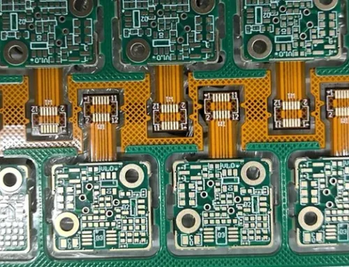
- Verify PTH quality for secure connections between flex and rigid boards.
Pro Tip: Pay attention to plated through holes in connector areas. Poor copper distribution can weaken mechanical strength over time.
The Hirose DF40 series is popular for compact, high-density FFC FPC board connectors.
Underestimating High-Speed Signal Challenges
Issue: At high frequencies, incorrect flexible PCB design can lead to EMI, signal reflection, and data loss. Moreover, this issue becomes especially critical in high-density designs.
Solutions:
- Apply controlled impedance rules (50Ω or 100Ω differential pairs).
- Embed ground planes and keep trace geometry consistent.
- Use copper-filled via fences for RF isolation.
- Consider additive manufacturing to integrate capacitors directly.
- Select smooth copper foil to reduce signal loss caused by surface roughness.
Data Point: A 10-layer automotive FPC board improved data integrity by 20%. This was achieved by optimizing the thickness of the dielectric layer and the roughness of the copper.
References: Roughness of Copper and Its Effect on Signal Integrity
5. Skipping Environmental Protection

Issue: Without proper environmental safeguards, flexible circuits are prone to premature failure from exposure to moisture ingress, mechanical vibration, and repeated thermal cycling.
Solutions:
- Apply acrylic or silicone conformal coatings to shield against contaminants.
- For thermal-heavy applications, use thermally conductive pads or adhesives.
- Test against standards like MIL-STD-810G and IEC 60068-2-30.
- Conduct a board bakeout to remove moisture before assembly.
Insight: Moisture can degrade solder joints and adhesives over time. Protecting your flexible PCBs with proper coatings extends field performance.
Printed Circuit Board Bake‑out Process and Quality Control
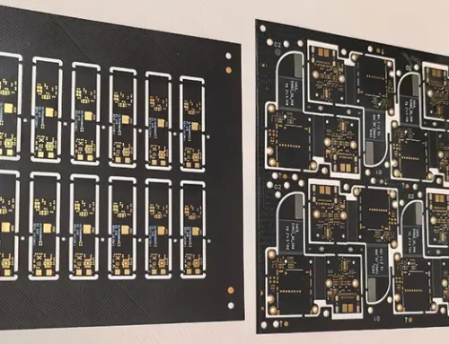
6. Design for Test and Manufacturability (DFM)
Issue: Skipping DFM reviews leads to costly rework, yield loss, and delays in time-to-market.
Solutions:
- Include test points and breakout pads for electrical validation.
- Perform pre-production checks: solder mask alignment, spacing, impedance.
- Use flex PCB extension boards during prototyping for modular debugging.
- Ensure that DFM reviews include flex-specific processes like coverlay lamination, plated through hole validation, and bend reliability.
Note: Rigid board rules alone do not apply. Flexible PCB design requires dedicated knowledge of materials, process tolerances, and assembly handling.
Conclusion: Minimize Mistakes, Maximize Success
Designing robust and cost-effective flexible printed circuit boards requires more than just selecting the right flex materials. Engineers must consider important design factors. These include bend radius, high-speed signal behavior, connector integration, and real-world mechanical stress.
Avoiding these six common pitfalls helps ensure scalable, durable, and reliable flex designs. No matter what type of flexible PCB you are making, using good design practices is important. This includes rigid flex PCBs, single-layer FPCs, and complex high-density interconnects.
Following best practices improves your flexible PCB design. It also brings clear benefits. These include lower costs, fewer failures, and faster product development.
✨ Need expert support? Gekun provides design consultation, prototyping, and production services for flex circuits and rigid flex PCBs. Contact us for a free review or DFM consultation.