Choosing the Right Flex Circuit Connector: Tips and Best Practices
Summary
Selecting the right flex circuit connector is essential for ensuring reliable electrical continuity, mechanical robustness, and efficient assembly in modern electronics.
This guide talks about the basics of connectors. It covers different types, like ZIF, FPC, FFC, and BTB. It also compares FPC and FFC connectors. Additionally, it goes into details about design, materials, how they connect, testing for the environment, and future trends. We include important keywords like fpc zif connector, fpc vs ffc connector, flex connector, btb connector, HRS connector, and lif zif connector. We left out any less important keywords.
Understanding Flex Circuit Connectors
A flex circuit connector connects flexible printed circuits (FPCs) or flat flexible cables (FFCs) to rigid printed circuit boards (PCBs) or other devices. It eliminates soldering or welding by using mechanical clamps or zero-insertion-force latches, simplifying production and serviceability. Flex connectors support tight bend radii and high-density interconnects in compact devices like smartphones, wearables, and medical probes.
Flex connectors come in different shapes. These include vertical, right-angle, and board-to-board (BTB) types. Each type serves specific flex technologies. Key terms include FPC connector, FFC connector, ZIF connector, flex connector, FPC ZIF connector, and BTB connector. Each variant addresses unique requirements in signal integrity, mechanical endurance, and environmental resistance.
What Is a Flex Connector?
A flex connector (or flexible printed circuit connector) is an electromechanical component designed to secure and electrically connect an FPC or FFC to another board or device. Connectors use features such as:
Zero Insertion Force (ZIF) mechanisms (e.g., lif zif connector) to prevent contact damage during insertion.
Mechanical clamps or robust housings (e.g., HRS Connector) for high-reliability applications.
Surface-mount or through-hole mounting to match PCB assembly processes.
By replacing bulky wire harnesses, flex connectors contribute to space optimization, weight reduction, and design flexibility—critical for aerospace, medical, and consumer electronics marketsMorePCB.
Types of Flex Circuit Connectors
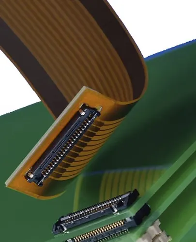
ZIF Flex Circuit Connector
ZIF Connector
Zero Insertion Force (ZIF) connectors let you insert the cable with almost no effort. A sliding latch or flip-lock then holds the FPC or FFC in place. Also called zif zero insertion force connector, a lif ZIF connector, or a ZIF type connector, these are ideal for:
Frequent mating cycles (service ports)
Delicate circuits where pad wear must be minimized
Configurable applications requiring tool-less assembly
Common names include ZIF FPC connector, ZIF FFC FPC connector, and ZIF ribbon cable connector. Typical pitches range from 0.25 mm to 1.0 mm, with various orientations (top- or bottom-contact)
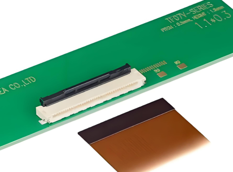
FPC Connector
FPC connectors are specifically engineered for flexible printed circuits (FPCs). They offer:
Fine pitch options (down to 0.25 mm)
Low profile heights (< 1 mm)
Variants like straight, right-angle, and dual-row configurations
Specialized battery interconnect types (e.g., FPC battery connector)
Choosing the right FPC connector footprint and pin count (like 6-pin or 34-pin) is important during PCB layout. This helps ensure proper connection and signal quality.
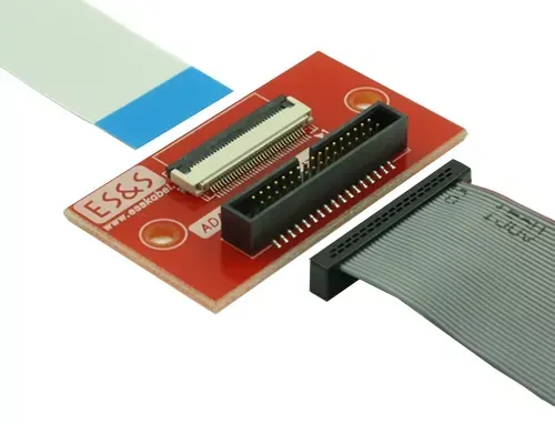
FFC Connector
Flat Flexible Cable (FFC) connectors accommodate ribbon-style cables with fixed conductor spacing. Differences from FPC connectors include:
Stiffer cable structure—better for static runs
Simplified cable assembly without custom circuit fabrication
Common in printers, scanners, and display modules
Often called FFC cable connectors, these connectors come in different pitches, like 0.5 mm and 1.0 mm, and latch types.
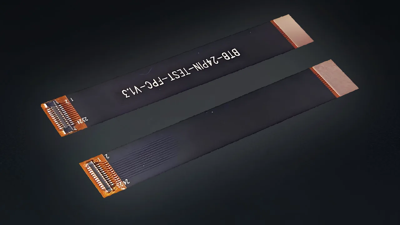
Board-to-Board (BTB) Connector
BtB Connector
While not directly connecting an FPC, BTB connectors (like mezzanine connectors) are used for rigid-flex PCB assemblies. In these assemblies, a flex tail plugs into a mating board stack-up. These high-density connectors have multi-row contacts. They also handle heat and vibration well, making them a good flex interface choice.
FPC vs. FFC Connector
Understanding the distinction helps optimize design:
| Feature | FPC Connector | FFC Connector |
|---|---|---|
| Cable substrate | Polyimide film (flex PCB) | Polyethylene or similar ribbon |
| Flexibility | High supports dynamic bending | Low—static bends only |
| Custom circuit patterns | Yes | No (straight conductors only) |
| Typical use | Touchscreens, cameras, and medical sensors | Printers, scanners, LCD modules |
| Pitch range | 0.25 mm–1.25 mm | 0.5 mm–1.0 mm |
Choosing between FPC and FFC connectors depends on your needs. If you want custom trace routing and flexibility, choose FPC. If you prefer a simpler ribbon connection, go with FFC.
Key Considerations When Choosing a Connector
Application Requirements
Environmental: Temperature extremes, moisture, vibration—important for aerospace and defense.
Cycle life: ZIF connectors offer 1000+ mating cycles; standard clamps may rate 50–100.
Automated assembly: SMT-compatible variants reduce manual labor and improve throughput.
Electrical Specifications
Current & voltage: Ensure connectors handle power levels, especially for FPC connector battery applications or flex circuit cable power lines.
Signal integrity: High-speed data (LVDS, HDMI) may require controlled impedance and shielding features.
Contact plating: Gold plating resists corrosion in harsh environments.
Physical Constraints
Footprint: Match the FPC connector footprint in your CAD library before fabrication.
Height & orientation: Low-profile (< 1 mm) connectors suit space-constrained designs.
Pin count & pitch: From fpc connector 6-pin to multi-row 34-pin flex tails for complex signals.
Material & Mechanical
Housing materials: High-temperature polymers (LCP, PPS) resist reflow profiles.
Retention force: Clamps vs. latches—choose based on shock and vibration requirements.
Stiffener integration: Add local reinforcement near solder joints to reduce stress concentrations during flexing (
Reference Post: Flex-circuit Soldering & Assembly Tutorial and Notes
Benefits of Using Flexible PCB Connectors
Space Optimization
Low-profile flex circuit edge connectors enable ultra-thin device packaging, crucial in wearables and smartphones.
Weight Reduction
Using flex cable connectors instead of wire harnesses can reduce assembly weight by up to 50%. This is important for aerospace and portable medical equipment.
Design Flexibility
Dynamic bend radii and multi-axis folding allow 3D assembly configurations, unlocking new form factors in industrial automation and robotics.
Common Applications of Flex Circuit Connectors
Consumer Electronics
Smartphones, laptops, cameras, and wearables rely on flexible PCB connectors for interconnects between display modules, touch sensors, and mainboards.
Medical Devices
Miniaturized diagnostic probes, implantable sensors, and handheld analyzers use FPC connectors to achieve biocompatible, sterilizable assemblies with reliable high-speed signals.
Aerospace and Defense
Robust flex circuit robust connector designs withstand extreme vibration, temperature cycling, and radiation exposure in avionics and satellite systems.
Installation Guidelines & Best Practices
Align Precisely: Use fiducials and alignment pins to ensure the FPC/FFC inserts squarely.
Bend Control: Route flex cables to respect minimum bend radii—typically 10× cable thickness.
Stiffener Use: Apply stiffeners at connector ends to reduce stress on the flex tail.
Proper Latch Engagement: Verify ZIF locks are fully closed to prevent intermittent contact.
Clean Contacts: Use isopropyl alcohol to remove debris before final assembly.
Maintenance, Repair, and Troubleshooting
Contact wear: After 500+ cycles, inspect for pad damage in ZIF connectors.
Cable replacement: Keep spares of FPC connector cable assemblies to minimize downtime.
Signal loss: Often remedied by reinserting the FPC and cleaning contacts.
Housing damage: Replace cracked latch mechanisms (common in budget connectors).
Environmental and Reliability Testing
Connectors in critical applications should undergo:
Thermal cycling: −40 °C to +85 °C, 1000 cycles to simulate field conditions.
Humidity testing: 85 % RH at 85 °C for 1000 hours to evaluate corrosion resistance.
Vibration & shock: IEC 60068 profiles to confirm mechanical retention under stress.
Manufacturers like TE Connectivity, Molex, and HRS Connector provide validated test reports to support qualification processes.
Future Trends in Flex Connector Technology
Micro-pitch connectors: Down to 0.2 mm for next-gen wearables and IoT sensors.
Integrated shielding: Embedded EMI/RFI barriers for high-speed flex data lines.
Smart connectors: On-board diagnostics (e.g., wear indicators) to predict end-of-life.
Bio-compatible materials: For implantable medical flex assemblies.
At Gekun, we manufacture high-reliability flexible circuit boards that leverage high-precision flex circuit connectors to enhance product quality, longevity, and performance. By integrating ultra-fine-pitch connectors and rigorously testing every assembly, we ensure your FPC solutions withstand demanding environments and extended service cycles. Contact us for custom FPC designs, precision integration guidance, or detailed technical datasheets tailored to your application


Leave A Comment