
PCB Drilling: Mechanical vs. Laser Techniques, Hole Types & Quality Insights
Introduction: Why PCB Drilling Matters More Than Ever
In modern electronics manufacturing, PCB drilling is not just a routine step. It is key for making vertical connections between copper layers. This process helps deliver high-performance signal routing.
As designs become smaller, 5G technology, and high-density applications increase, the quality of holes in PCBs is important. It impacts product reliability, yield, and thermal management.
This article explores drilling techniques for PCB boards. It covers hole types, drilling parameters, and equipment selection. It also addresses special needs for flexible circuit boards.
What is PCB Drilling and Why It’s Crucial
PCB drilling is the process of making holes in PCBs. This helps connect different layers electrically or hold components in place. It’s a key process in making multi-layer and rigid-flex PCBs. It allows signals and power to move up and down through stacked layers of copper.
Holes may be drilled for various functions:
Plated through holes (PTH): Connect all copper layers.
Via holes: For signal routing between selected layers.
Mechanical component holes: For mounting connectors or heat sinks.
Selecting the right drilling method ensures not only electrical continuity but also structural integrity and long-term performance.
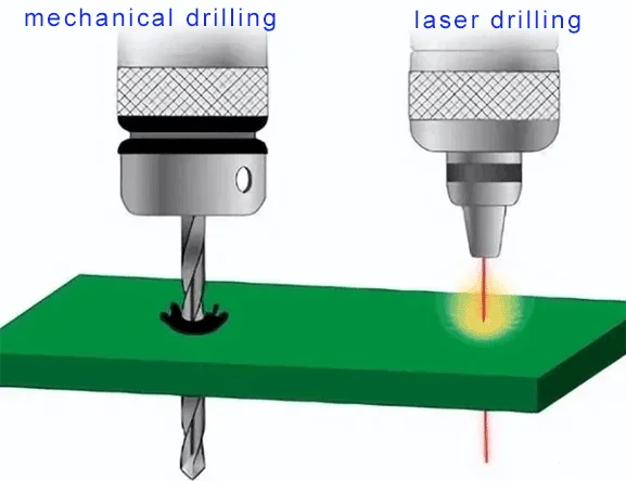
Mechanical Drilling: Traditional but Trusted
Mechanical drilling remains the industry workhorse, especially for rigid PCBs and larger hole sizes (≥ 0.15 mm). The process uses carbide or diamond-coated drill bits in high-speed drilling machines.
Advantages:
Lower capital investment.
Suitable for PTH, standard vias, and large-scale production.
Challenges:
Drill bit wear is affecting accuracy and increasing tool replacement costs.
Heat generation and potential delamination in multi-layer boards.
Requires precise control of drilling parameters like spindle speed and feed rate.
For flexible circuit boards, engineers must carefully tune mechanical drilling to avoid stretching or damaging the substrate. People often use special vacuum fixtures to secure the panels.
Laser Drilling: Precision for HDI and Flex Circuits
Laser drilling is a method that makes holes using CO₂ or UV laser beams. This process allows for very precise holes without using mechanical force. It is ideal for microvias (≤ 0.1 mm), especially in HDI and flexible PCBs.
Key Benefits:
No physical contact, reducing mechanical stress.
High-speed drilling—thousands of holes per second.
It supports ultra-small hole diameter, which is essential for modern devices.
Considerations:
Higher initial equipment investment.
Limited to thin dielectric layers (ideal for flex circuits).
Use Cases:
Smartphones, wearable devices, 5G modules, and any miniaturized product where high quality, density, and reliability are essential.
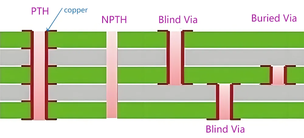
Types of Holes in PCBs
Understanding the different hole types is critical for engineers and PCB designers:
| Hole Type | Description |
|---|---|
| Through-Hole | Extends through the entire board; used for leads and interconnects |
| Blind Via | Connects the outer layer to the inner layer; doesn’t go through the whole board |
| Buried Via | Links internal layers; not visible from the board surface |
| Microvia | Laser-drilled micro-holes for HDI applications |
| Back-Drilled Hole | Removes unused copper layers in PTH to improve signal integrity |
Type of PCB Drilling
PTHs are the most common holes in PCBs, where the inner wall of the hole is coated with conductive copper plating.
- They provide electrical connectivity between the top, bottom, and inner copper layers.
- The whole wall integrity and copper plating thickness directly affect the reliability of the,
For flexible circuit boards, engineers must manage hole wall integrity carefully to prevent cracking under bending or thermal cycles.
Non-Plated Through Holes (NPTH)
These holes are used for mechanical purposes such as mounting components or the s.
- NPTH does not have any copper plating.
- They do not participate in the electrical performance of the PCB..
Reference post: Plated and Non-Plated Trough Holes
Key Drilling Parameters that Influence Quality
Drilling is a high-speed, precision process. Each parameter impacts the final board quality and cost:
Drill Bits: Shorter, more rigid bits reduce deflection and positional inaccuracy.
Spindle Speed: Higher RPMs improve cutting but may increase heat. It must be tuned based on the material.
Feed Rate: If too fast, it causes smearing or cracking; if too slow, it lowers productivity.
Depth Control: Essential for blind and buried vias—over-drilling ruins the layer below.
Desmear Process: Chemical removal of resin to ensure copper plating adheres well.
Hole Diameter Tolerance: Must be tightly maintained to fit component leads and plating requirements.
Step-by-Step: PCB Drilling Process Flow
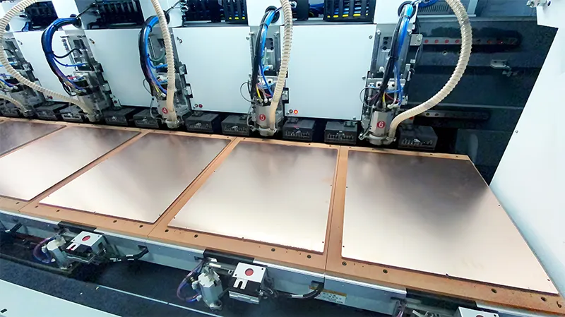
Here’s how PCB manufacturers execute precision drilling:
Panel Fixation: Secure rigid or flex panel using fixtures.
Pre-Drilling: Use short blades to test alignment.
Main Drilling: Execute full-depth drilling using mechanical or laser tools.
Deburring: Remove smears and roughness from drilled holes.
Desmear: Clean resin residue chemically (e.g., KMnO₄).
Plated Through Hole (PTH) Process: Electroless copper followed by electroplating.
Quality Inspection: Inspect hole wall smoothness, positional accuracy, and CPK metrics.
Reference post: PCB Drilling Process: The Cornerstone of Precision
Key Drilling Parameters That Affect Hole Quality in PCB Manufacturing
In high-precision PCB manufacturing, especially for multilayer and HDI designs, drilling quality directly impacts electrical performance and long-term reliability. Several critical parameters influence the final hole integrity, copper plating adhesion, and via functionality. Optimizing these drilling parameters is essential to maintain tight tolerances and ensure robust interconnections.
Here’s a summary of the most impactful drilling parameters:
| Drilling Parameter | Effect on Hole Quality |
|---|---|
| Drill Bits | Using short, rigid drill bits minimizes deflection, improving hole position accuracy. |
| Spindle Speed | Higher RPM increases cutting efficiency but generate more heat, risking resin smear. |
| Feed Rate | Too fast can cause delamination, smearing, or cracks; too slow leads to low productivity. |
| Depth Control | Critical for blind and buried vias to avoid overdrilling and ensure layer-specific contact. |
| Desmear Process | Chemical resin removal (e.g., KMnO₄) ensures clean walls and optimal copper plating adhesion. |
| Diameter Tolerance | Maintaining design tolerances is vital to ensure proper component fit and soldering. |
You must carefully adjust each of these parameters during the PCB drilling process. This ensures the final product meets IPC standards for via reliability and electrical performance. Poor control of drilling conditions can lead to open circuits, low plating quality, or misalignment. This is especially true in flexible or rigid-flex PCB applications with dense layer stacking.
Mechanical vs. Laser: Choosing the Right Drill for PCB Board
The image is from the internet
| Factor | Mechanical Drilling | Laser Drilling |
|---|---|---|
| Hole Size | ≥ 0.15 mm | ≤ 0.1 mm (microvias) |
| Cost | Lower equipment, higher wear | High initial investment |
| Speed | Moderate | Ultra-fast (ideal for HDI) |
| Accuracy | Moderate | Extremely high |
| Suitable Applications | PTH, standard boards | HDI, flex circuits, micro-components |
| Thermal Impact | High | Low (safe for flex materials) |
Takeaway: For high-density or flex PCBs, laser is not optional—it’s essential. For low-cost, low-density boards, mechanical is still viable.
Reference post: PCB Laser Drilling: A Comprehensive Guide
How PCB Drilling Affects Cost, Yield, and Performance
Every drilled hole has implications:
Signal Integrity: Poor hole geometry or stubs lead to reflection and loss in high-speed signals.
Yield Impact: Misaligned or poorly plated holes increase scrap and rework.
Production Time: Complex drilling, like back drilling or buried vias, adds steps.
Cost: Wear and tear on drill bits, longer lamination cycles, or expensive laser systems raise costs.
Especially in flexible circuit boards, tolerance to stress and heat is low, making precision drilling mandatory.
Conclusion: Optimizing Drilling for Today’s PCB Demands
As electronics evolve, so does the complexity of PCBs. High-speed signals, tighter spaces, and flexible formats demand precision drilling. Choosing between mechanical and laser drilling depends on hole size, board type, and performance needs.
At Gekun, we use both methods based on your needs. This ensures high quality, speed, and cost-efficiency for every printed circuit board.
FAQs and Terminology: PCB Drilling Essentials
What is PCB drilling?
The creation of holes in PCBs to allow electrical or mechanical interconnection.
What are plated through holes (PTH)?
Holes that connect all layers of a PCB, filled with copper plating.
What’s the demerit process?
Chemical cleaning to remove resin smears, ensuring better copper adhesion.
When to use laser drilling?
Use it for small holes (< 0.1 mm), HDI boards, or flex circuits needing ultra-fine features.
How do I select drill bits?
Based on board thickness, hole size, and material type, carbide is common.
What is a back-drilled hole?
A partially drilled hole is used to remove unused copper stubs in high-speed designs.


Leave A Comment