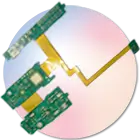
Single-Sided Flex PCB
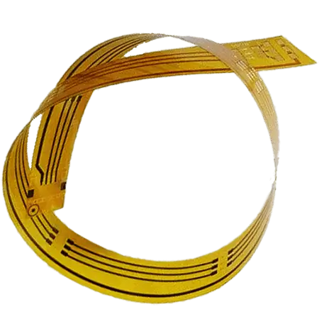
A single-sided flex PCB is a type of board. It has one layer of conductive material. This layer is on a flexible base material-polyimide (PI) or polyester (PET).
That layer could be made of copper or a metal-filled polymer. This would create circuitry on just one side. Because it is flexible, it is often used in tight spaces where lightweight and high flexibility are needed.
Flexible circuits, like single-sided flex circuits, can bend and flex. This makes them a great choice for dynamic applications.
They are ideal for wearables, medical devices, and automotive uses. Such circuits are commonly used where small size and resistance to movement are important. Their slim design allows for use in high-density connections. This is important for applications that need a compact and reliable link.
Single-Sided Flex PCB Stack-Up Example
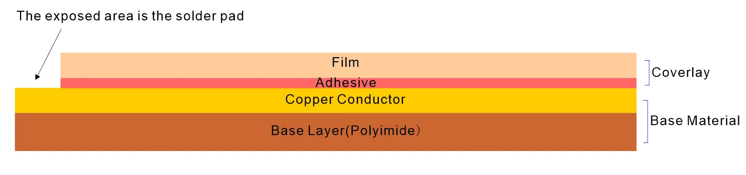
single-sided flex pcb stack-up image
A typical single-sided flexible PCB stack-up includes:
Coverlay (PI Film) – Encapsulates and insulates the circuit.
- Adhesive – Binds copper to the film.
Copper Conductor (1 oz) – Transfers signals and power.
Base Layer: It consists of Polyimide (25–50 μm)-Core Flexible Substrate.

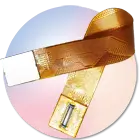
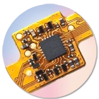
Single-sided flex PCB 3D image

Overall Thickness: ~0.1mm to 0.3mm (+/-0.03mm – thickness varies primarily due to copper thickness and layer options).
Thermal Considerations:
Thin materials restrict thermal flow, making thermal management a challenge. In higher power applications, incorporating thicker copper or external heat-spreading films can improve performance. Consider this during flex circuit design, especially for power-intensive systems.
Note: In most cases, the Base layer (PI) and Copper bought by flexible circuit board factories come together. They are usually called Base materials
Also, Adhesive and Film are integrated, known as Coverlay Film
Structure of a Single-Sided Flex PCB vs Double-Sided Flex PCB

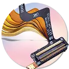
Double-sided flex PCB stack-up
“Single-sided flex PCB stack up “refers to the previous chapter.
| Layer/Feature | Single-Sided Flex PCB | Double-Sided Flex PCB |
|---|---|---|
| Base Material | PI (Polyimide) or PET (Polyester) | Same as single-sided |
| Copper Layer | Single conductive layer (one side only) | Two copper layers (Top & Bottom) for complex routing |
| Adhesive | Optional (bonds copper to substrate) | Same as single-sided, but applied on both sides |
| Coverlay | PI film for mechanical protection | Dual-sided coverlay for enhanced protection |
| Plated Through-Holes (PTH) | Not applicable (single-layer design) | Present (electrically connects both layers) |
Layer Architecture
Single-sided designs utilize one conductive copper layer on a polyimide (PI) or polyester (PET) base, suitable for simple circuits.
Double-sided variants incorporate two interconnected copper layers, enabling complex routing for advanced applications.
Critical Components
Coverlay protection: Both types use polyimide films, but double-sided PCBs require dual-layer application.
Interlayer connections: Only double-sided designs feature plated through-holes (PTH) for vertical conductivity between layers.
Note: The single-sided and double-sided design all allows for multi-level flex solutions. You can layer or bond layers for multi-level (redundant) interconnects.
Single-Sided Flex Circuit vs Single-Sided Rigid Circuit: The Differences

sigle sided flex vs rigid PCB stack up
| Feature | Single-Sided Flex PCB | Single-Sided Rigid PCB |
|---|---|---|
| Material | Polyimide or polyester film | FR4 or fiberglass |
| Flexibility | Highly bendable and twistable | Completely rigid |
| Weight | Extremely lightweight | Comparatively heavier |
| Heat Dissipation | Limited due to thin construction | Better heat management |
| Applications | Wearables, medical, foldable electronics | Consumer and industrial products |
| Durability | Resilient to vibration and movement | Can crack under physical stress |
| Controlled Impedances | Difficult to manage | Easier due to thicker layers |
| Cost | Higher due to specialized materials | Lower with conventional methods |
Key Takeaway:
If your application requires flex circuit design for dynamic environments, the single-sided flex PCB is ideal. For applications requiring structural rigidity and high thermal resistance, rigid boards are preferable.
More information: Rigid PCB vs Flexible PCB: Which Wins for Your Applications?
How to Make a Single-Layer Flex PCB?
Step-by-Step Manufacturing Process

- Material Selection
Choose appropriate base film and copper foil based on flexibility, temperature requirements, and final application. - Drill hole
This hole is not used for circuit conduction. Instead, it is a positioning hole needed for production and processing - Circuit Patterning
Apply photoresist and use UV light to define copper traces.
Use etching or laser cutting for precise circuit definition. - Coverlay Application
Laminate polyimide film to encapsulate the circuit. - Electrical Testing & Visual Inspection
Critical for ensuring performance and detecting shorts or open circuits.
Flex PCB Design Guidelines:
- Avoid sharp corners to prevent stress fractures.
- Use staggered trace routing for better flexibility.
- Optimize trace width and spacing for signal integrity and controlled impedance.
- Employ dynamic bend simulation in design to improve product longevity.
When to Use Single-Layer Or Double-Sided Flexible PCB?
For a cost-effective, low complexity solution, single-sided flex circuits are often an ideal choice.
- A double-sided flex PCB provides excellent route guidance and better electrical performance. It works well in high-density systems, such as industrial automation and medical devices.
Pro Tip Time: If signal routing and electromagnetic shielding are paramount, consider multi-layered flex designs.
How Thick is a Single Layer Flex PCB?
The overall thickness of a single-layer flex PCB varies based on several components:
Base: Typically 12.5-50 µm.
Copper Weight: 0.5 oz (17 µm) to 2 oz (70 µm).
Adhesive & Coverlay: That’s an additional 25-50 µm.
Overall Thickness: About 0.05 mm- 0.3 mm.
Performance Impact:
Thinner constructions allow greater flexibility but reduce thermal resistance.
Thicker copper increases current-carrying capacity but limits bending radius.
Applications of Single-Sided Flex PCBs
Single-layer flexible circuits are widely used in:
Wearable Electronics: Smartwatches, health monitors, smart glasses.
Medical Devices: Endoscopes, hearing aids, portable diagnostics.
Automotive Applications: Flexible lighting, in-dash sensors, and display modules.
Consumer Electronics: Foldable phones, digital cameras, Bluetooth earbuds.
Key Advantages:
Compact and lightweight – ideal for miniaturized electronics.
High reliability in movement-heavy applications.
Tailorable to unusual shapes and enclosures.
Additionally, it offers easier assembly compared to complex rigid-flex solutions.
These benefits make flexible printed circuit boards essential in today’s trend toward smaller, more mobile electronic devices.
Conclusion
Rigid-Flex Single Sided flexible PCBs are a great solution. They work well for simple connections and tight spaces. They can survive bending, fit into tight spaces, and provide steady electrical performance. Therefore, they are a top choice for many growing markets, such as wearables, automotive, and medical applications.
As materials and design tools get better, flex circuits will grow. So, this includes both single and multi-layer flex circuits. They will push the boundaries of today’s electronics design.
Double Sided Flex
Multilayer Flex PCB
Rigid Flex PCB
Flex PCB Assembly
GK Flexible Circuits is a leading global supplier specializing in the design and production of
Flexible circuit boards, Rigid-Flex PCB, and PCB Assembly components in China
Get A Quote


