
PCB Trace Width and Current Relationship: Calculation, Data, and Exper
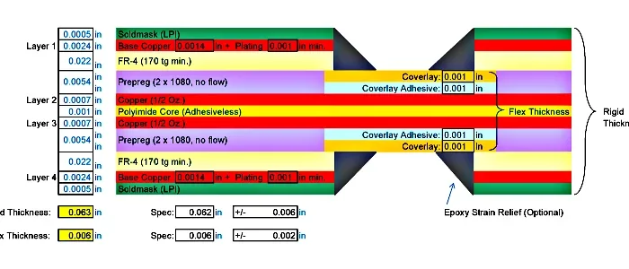

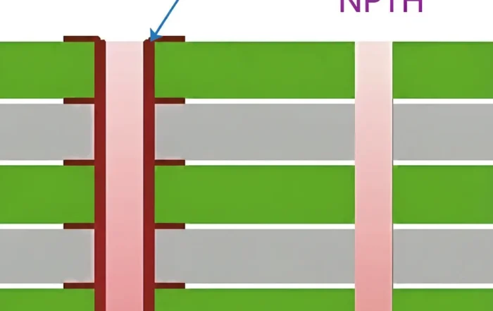

In PCB design, current-carrying capacity is one of the most misunderstood yet most critical parameters—particularly in power electronics, motor drivers, and high-current control systems. Signal integrity, impedance control, and EMC often receive significant attention, while trace current capacity is frequently reduced to rough rules of thumb or “experience-based judgment.” That works—until it doesn’t.
Unlike wires, PCB traces are constrained by copper thickness, trace width, thermal dissipation paths, solder coverage, pad geometry, and manufacturing variability. A trace that looks sufficient under steady state can fail during transient overloads, short circuits, or surge events, with consequences ranging from localized trace burnout to cascading failures across power and signal domains.
This document consolidates empirical formulas, industry reference data, experimental observations, and hard-earned design lessons for PCB current-carrying capacity. The same empirical formulas also suit Flex PCB and other board types. It explores copper thickness, trace width, temperature rise, solder reinforcement, pad and via geometry, and transient current behavior, and it highlights why seemingly minor layout choices—such as pad spoke patterns—can determine whether a design survives a fault condition or self-destructs in microseconds.
Calculation Method:
First, calculate the cross-sectional area of the track. Most PCB copper foil thickness is 35μm (if uncertain, consult the PCB manufacturer; 1 oz = 35μm, though actual thickness is typically less than 35μm).
Multiply this by the line width to obtain the cross-sectional area, ensuring conversion to square millimeters.
An empirical current density value ranges from 15 to 25 amperes per square millimeter.
Multiply this by the cross-sectional area to obtain the current-carrying capacity. I = K × T⁰.⁴⁴A⁰.⁷⁵ (K is the correction factor:
typically 0.024 for copper-clad layers on inner layers and 0.048 for outer layers) T is the maximum temperature rise in degrees Celsius (copper’s melting point is 1060°C) A is the copper-clad cross-sectional area in square mils (Note: square mil, not mm).
I represents the maximum allowable current in amperes (A). Typically, 10 mil = 0.010 inch = 0.254 mm corresponds to 1 A, while 250 mil = 6.35 mm corresponds to 8.3 A.
Data:
Calculating PCB current-carrying capacity has long lacked authoritative technical methods or formulas. Experienced CAD engineers can make relatively accurate judgments based on personal expertise.
However, for CAD novices, this presents a significant challenge. PCB current-carrying capacity depends on the following factors: trace width, trace thickness (copper foil thickness), and allowable temperature rise.
It is widely understood that wider PCB traces carry greater current. Here, consider this: assuming identical conditions, if a 10MIL trace can handle 1A, would a 50MIL trace handle 5A? The answer is clearly no.
Refer to the following data provided by an international authoritative body:
- Unit for trace width: Inch (inch = 25.4 millimeters)
- 1 oz. copper = 35 microns thick, 2 oz. = 70 microns thick
- 1 OZ = 0.035mm
- 1mil. = 10⁻³ inch.
Experiment
Experiments must also account for voltage drops caused by wire resistance due to length. Solder applied during process soldering merely increases current capacity but makes precise volume control difficult. A 1-oz copper wire, 1mm wide, typically handles 1-3 A currents, depending on wire length and voltage drop requirements.
The maximum current rating refers to the permissible value under temperature rise constraints, while the fuse value indicates the current at which the temperature rise reaches copper’s melting point. Eg. 50mil 1oz with a temperature rise of 1060°C (copper’s melting point) corresponds to a current of 22.8A.

Table 1
Relationship Between PCB Copper Thickness, Trace Width, and Current
Before exploring the relationship between PCB copper thickness, trace width, and current, let’s understand the conversion between ounces, inches, and millimeters for PCB copper thickness: “In many datasheets, PCB copper thickness is often specified in ounces. The conversion between ounces, inches, and millimeters is as follows:
- 1 oz = 0.0014 inches = 0.0356 millimeters (mm)
- 2 oz = 0.0028 inches = 0.0712 millimeters (mm)
Ounces are a unit of weight. The conversion to millimeters is possible because PCB copper thickness is measured in ounces per square inch.”

Table 2 PCB Design Copper Thickness, Line Width, and Current Relationship Table.
The current-carrying capacity of a conductor is directly related to the number of vias and pads present on the conductor line (currently, no formula has been found to calculate the impact of pads and via apertures per square millimeter on the line’s current-carrying capacity; interested individuals may research this further, as I am not entirely clear on this and will not elaborate here).
Here, we will briefly outline some primary factors affecting a line’s current-carrying capacity.
1. The current carrying capacity values listed in the table represent maximum values at standard room temperature (25°C). Actual design must account for environmental conditions, manufacturing processes, substrate materials, board quality, and other variables. Therefore, the table provides reference values only.
2. In actual design, each conductor is also affected by pads and vias. For instance, segments with numerous pads will see a significant increase in current-carrying capacity at the pad locations after solder wetting. Many have likely observed sections of trace between pads being burned out on high-current boards.
The reason is straightforward: after solder wetting, the presence of component leads and solder enhances the current-carrying capacity of that segment.
However, the maximum current a pad-to-pad connection can handle is limited by the maximum current the pad width permits.
Consequently, during instantaneous circuit surges, the pad-to-pad segment is prone to burning out. Solutions: Increase the trace width. If the board does not permit widening the trace, add solder layer to the trace (typically, a 1mm trace can accommodate an additional solder layer trace of about 0.6mm; alternatively, you can add a 1mm solder layer trace).
After solder overpass, this 1mm trace can be considered equivalent to a 1.5mm~2mm trace. (Depending on solder distribution uniformity and volume during soldering), as shown below:

Figure 1
Such techniques are familiar to those designing small appliance PCBs. With sufficiently uniform and abundant solder coverage, this 1mm trace can effectively function as a 2mm trace. This aspect is particularly crucial in single-sided high-current boards.
3. The treatment around the pads in the diagram similarly enhances the uniformity of current-carrying capacity between the conductor and the pad.
This is especially important in boards with thick, high-current leads (where the lead width exceeds 1.2mm and the pad diameter is over 3mm).
If a pad exceeds 3mm and the pin exceeds 1.2mm, the current flowing through this pad after soldering increases by several dozen times.
During high-current surges, the current distribution across the entire circuit becomes highly uneven (especially with numerous pads), significantly increasing the risk of burnout between pads.
The approach shown in the diagram effectively distributes the current load across individual pads and surrounding traces, improving uniformity.
Finally, note: Current carrying capacity data sheets provide absolute reference values.
For non-high-current designs, adding 10% to the specified values will fully meet design requirements.
For typical single-sided PCB designs with 35μm copper thickness, a 1:1 design ratio is generally sufficient.
This means a 1mm conductor can handle 1A current while meeting requirements (calculated at 105°C).
Relationship Between PCB Copper Foil Thickness, Trace Width, and Current
Use the PCB trace width current table below to compare copper thickness and width combinations, then adjust the selected row for layer position, allowable temperature rise and actual manufacturing tolerance.
Signal Current Intensity. When the average signal current is high, consider the current capacity of the trace width. Trace widths can be referenced from the following data:
Current carrying capacity for copper foils of different thicknesses and widths is shown in the table below:

Table 4 Relationship Between Copper Foil Thickness, Trace Width, and Current in PCB Design
Notes:
i. When using copper foil as conductors for high currents, the current-carrying capacity of the foil width should be selected by derating the table values by 50%.
ii. In PCB design and manufacturing, OZ (ounce) is commonly used as the unit for copper foil thickness. 1 OZ copper thickness is defined as the weight of copper foil per square foot, corresponding to a physical thickness of 35μm; 2OZ copper thickness is 70μm.
Empirical Formula
I = K × T⁰.⁴⁴A⁰.⁷⁵
K is the correction factor, typically 0.024 for copper-clad traces on inner layers and 0.048 for outer layers. T is the maximum temperature rise in degrees Celsius (copper’s melting point is 1060°C).
A is the copper-clad cross-sectional area in square mils (not square millimeters).
I is the maximum allowable current in amperes (A).
Typically, 10 mil = 0.010 inch = 0.254 mm corresponds to 1 A; 250 mil = 6.35 mm corresponds to 8.3 A.
Calculation method provided by a netizen:
First, calculate the track cross-sectional area. Most PCB copper foil thicknesses are 35μm (if uncertain, consult the PCB manufacturer). Multiply this by the line width to obtain the cross-sectional area, ensuring conversion to square millimeters.
An empirical current density value of 15–25 amperes per square millimeter applies. Multiply this by the cross-sectional area to determine the current-carrying capacity.
Insights on Trace Width and Via Fill
When designing PCBs, we generally follow a common practice: use thicker traces (e.g., 50 mil or larger) for high-current paths, and thinner traces (e.g., 10 mil) for low-current signals.
For certain electromechanical control systems, instantaneous currents exceeding 100A may flow through traces. In such cases, narrower traces will inevitably fail.
A fundamental rule of thumb is: 10A/mm². This means a trace with a cross-sectional area of 1 square millimeter can safely carry 10A. If the trace width is too narrow, it will burn out under high current.
Of course, current-induced trace burnout follows the energy formula: Q = I²t. For instance, a trace carrying 10A can withstand a 100A current spike lasting microseconds—a 30mil trace would certainly survive.
(This raises another issue: the trace’s stray inductance. This spike will generate a strong counter-electromotive force due to this inductance, potentially damaging other components. Thinner and longer traces have greater stray inductance, so practical design must also consider trace length comprehensively.)
Most PCB design software offers several options for routing copper pads around component vias:
Right-angle radiating pads, 45-degree radiating pads, and straight pads. What’s the difference? Beginners often overlook this, choosing randomly based on aesthetics.
This is unwise. Two key considerations exist: preventing excessive heat dissipation and ensuring adequate current-carrying capacity.
Using straight pads significantly enhances the pad’s current-carrying capacity. This method is essential for device pins in high-power circuits.
Simultaneously, it offers excellent thermal conductivity. While beneficial for device cooling during operation, this poses challenges for PCB soldering personnel.
The pads dissipate heat too rapidly, making it difficult to hold solder. This often requires higher-wattage soldering irons and elevated soldering temperatures, reducing production efficiency.
Using right-angle or 45-degree radiating pads reduces the contact area between the pin and copper foil, slowing heat dissipation and making soldering much easier.
Therefore, selecting between straight or angled via pads for copper plating should be based on application requirements, balancing both current-carrying capacity and heat dissipation.
Avoid straight plating for low-power signal lines, while high-current pads absolutely require straight plating. Whether to use right-angle or 45-degree pads is primarily an aesthetic choice.
Why bring this up? Because I’ve been troubleshooting a motor driver for some time now. The H-bridge components kept burning out, and for four or five years, I couldn’t pinpoint the cause.
After much effort, I finally discovered: it turned out that during copper plating, the pad for one component in the power circuit used a straight-angle spoke pattern (and due to poor plating execution, only two spokes actually appeared).
This drastically reduced the power circuit’s overcurrent capacity. While the product functioned perfectly under normal 10A operation, a short circuit in the H-bridge would draw around 100A.
These two traces would instantly burn out (within microseconds).
Consequently, the power circuit becomes open-circuited. The energy stored in the motor, lacking a discharge path, dissipates through every possible route.
This energy surges through the shunt resistor and related operational amplifier components, obliterates the bridge control chip, and infiltrates the signal and power lines of the digital circuitry, causing catastrophic damage to the entire device.
The entire sequence unfolds with the same breathtaking intensity as detonating a massive landmine with a single strand of hair.
Other related Knowledge
Copper Thickness, Layer Position, Temperature Rise and Derating
Layer position changes the answer, because K differs. Outer layers use 0.048 and inner layers use 0.024. For the same current, an inner trace therefore needs more copper area. Inner copper also has less access to air and surface cooling, so the inner-layer penalty is not just a formula constant. In multilayer and Rigid-Flex PCB builds, that penalty adds up quickly, so plan the stackup early; the Rigid-Flex PCB Technology section shows how those builds are organized.
Copper thickness changes width directly. For the same current and allowed rise, the required copper area stays roughly similar, so width is roughly inversely proportional to copper thickness. A 2 oz layer can use a narrower trace than 1 oz, but etch factor, minimum spacing, stiffness and heat spreading still matter. A 0.5 oz layer needs more width and deserves more derating. Always use the real copper thickness, not only the nominal weight.
Temperature rise is the design variable, not the melting point. Copper melts at 1060 °C, which is far above any working board. The real limit is the rise you are willing to allow. Set the allowed rise from the maximum ambient and the maximum safe trace temperature. If ambient is 70 °C and the trace should not exceed 90 °C, the allowed rise is 20 °C, not 10 °C. Do not use ambient as the rise value in the formula. For higher ambient, either reduce current, widen the trace, add copper, or use a lower allowed rise. A common derating method is to size for 80% of the calculated current, or to add 20% to 30% width, and then verify the hot spot. High-reliability designs often need more margin than a quick calculator suggests.
Trace Length, Resistance and Voltage Drop
Trace width alone is not a complete design check. Length sets resistance, and resistance sets voltage drop and power loss. Use R = ρL/A, where ρ is copper resistivity, L is trace length and A is cross-sectional area. Then check Vdrop = I × R and P = I²R. A trace that is wide enough for current may still fail a rail tolerance because it is too long. This is common on low-voltage rails, remote loads, battery paths and power-entry sections. Check the voltage drop at maximum current and at maximum ambient, then compare it with the load budget. If the drop is too high, widen the trace, shorten the path, use a copper pour, add parallel layers, or move the regulator closer to the load.
Real Bottlenecks: Vias, Pads, Neck-Downs, Thermal Relief and Fuse Current
A straight trace can pass the width check and still fail at a via, pad, neck-down or thermal relief. A via barrel is a small cylindrical conductor, with area roughly π × drill diameter × plating thickness. However, a small via can carry much less current than the trace that feeds it. For high current, use multiple vias, larger drill, thicker plating or filled vias, and check the via-to-plane connection. Pads and neck-downs can be narrower than the incoming trace, so the bottleneck may sit right at the component footprint. Thermal relief spokes are useful for soldering, but the spokes can be the narrowest current path; add more spokes or use direct connection where thermal relief is not required.
Fuse current is another practical limit. A trace can heat and fuse under a short circuit, but you should not rely on a PCB trace as a fuse unless it is designed and tested for that role. Check fault current, source impedance and the energy the trace may see. A transient that lasts milliseconds can still create a local hot spot. Review pads, vias, spokes and neck-downs as current paths, not only the straight run.
Transient Overload and Fault Current
Trace width alone does not decide survival. A trace that looks fine at steady state can fail in a transient overload, a short circuit or a surge event. The damage is often non-linear: one local burnout can cascade across power and signal domains. Pad spoke patterns are a good example. A minor layout choice can decide whether a design rides out a fault or self-destructs in microseconds. Via geometry and via fill belong in the same review. For demanding programs, High-Reliability Flexible Circuits for High-End Applications outlines the reliability expectations.
FPC Trace Current Capacity in Flex Designs
The same empirical formulas also suit Flex PCB and other board types. FPC trace current capacity, however, deserves extra caution. Flex copper is thin, the base film spreads heat poorly, and solder reinforcement or stiffeners change local behavior. In many flexible circuit boards, power and signal traces share the same thin copper layer, so local heating is concentrated. Pad geometry and coverlay openings also control how much heat escapes. For high-current flex work, review High-Shielding FPCB methods before you lock the layout. Add copper pours, wider power traces, stiffeners and thermal vias where the construction allows.
Design Checklist for Trace Width and Current
- Confirm copper thickness with the manufacturer before you size the trace.
- Use the table as a first pass, never as the final answer.
- Cross-check with the formula and keep A in square mils.
- Use IPC-2152-based checks for final high-current or thermally critical designs.
- Apply a lower current density for inner layers and for flex circuits.
- Check voltage drop and power loss over the full trace length.
- Review pads, vias, spokes, neck-downs and thermal relief, not only the straight run.
- Plan for transient and fault current, then verify with PCB testing methods.
- Keep design margin for copper thickness, etch and plating tolerance.
Validation Loop: Simulation, Thermal Imaging, Measurement and Design Margin
Close the loop before release. Simulate the power path with an IPC-2152-based calculator or a thermal FEM model, then build a prototype and run it at maximum load and maximum ambient. Use a thermal camera to find hot spots at vias, pads, neck-downs and thermal relief. Measure voltage drop at rated current and compare it with the rail budget. Check manufacturing tolerance: trace width can vary with etch, copper thickness can be below nominal, and via plating thickness can vary. A practical design margin is 20% to 30% extra current capacity for many products, and more for high-reliability or high-ambient designs. If measurement disagrees with calculation, trust the measurement and find the missing thermal path or bottleneck.
Conclusion
PCB current-carrying capacity cannot be accurately reduced to a single number or simplistic linear scaling rule. While empirical formulas and reference tables provide valuable guidance, real-world performance depends on a complex interaction of geometry, thermal conditions, manufacturing processes, and transient electrical behavior.
Key lessons emerge clearly:
Trace width does not scale linearly with current—a 50 mil trace does not carry five times the current of a 10 mil trace under identical conditions.
Temperature rise, not copper melting point, defines safe operating limits, and conservative derating is essential in high-reliability designs.
Pads, vias, solder coverage, and spoke geometry significantly alter current paths, often becoming the weakest link during surge or fault conditions.
Transient currents and stored energy (I²t effects) can destroy traces in microseconds, even when steady-state operation appears safe.
Layout decisions intended for manufacturability or aesthetics can unintentionally cripple overcurrent robustness, as demonstrated by real-world motor driver failures.
Ultimately, high-current PCB design is not just about making traces wider—it is about designing predictable current paths, uniform thermal behavior, and controlled failure modes.
A robust design anticipates abnormal conditions, provides safe discharge paths for stored energy, and ensures that no single overlooked detail can turn a minor fault into total system destruction.
In power electronics, copper is not just a conductor—it is a safety mechanism. Treat it with the same rigor as any active component, and your designs will survive not only normal operation, but the rare and violent moments that truly test them.
FAQ
Does doubling the trace width double the current capacity?
No. The PCB trace width and current relationship is not linear. A 250 mil trace is 25 times wider than a 10 mil trace, yet it carries about 8.3 times the current under the same conditions. The formula exponent on area is 0.75, so capacity rises more slowly than width. Treat every table value as a starting point tied to its own copper thickness and allowed temperature rise.
Why do inner layers carry less current than outer layers?
The correction factor K in the empirical formula is 0.048 for outer-layer copper and 0.024 for inner-layer copper. Inner copper sits inside the board, so the same cross-sectional area returns a lower current result, and it also has less surface cooling. Always state the layer when you quote a current rating.
How does copper thickness change the required trace width?
For the same current and allowed rise, the required copper area is roughly similar, so width is roughly inversely proportional to copper thickness. A 2 oz layer can use a narrower trace than 1 oz, but check etch, spacing and heat spreading. A 0.5 oz layer needs more width. Use the real copper thickness, because nominal foil is often slightly thick or thin.
What temperature rise should I design for?
A 10 °C rise is a common starting point for general electronics, but the right value depends on maximum ambient, laminate rating, enclosure and reliability target. If ambient is high, set the allowed rise from the maximum safe trace temperature minus ambient. Do not use ambient as the rise value. High-reliability designs often add 20% to 30% current margin.
How does trace length affect current capacity and voltage drop?
Length does not change the cross-section that sets the basic current rating, but it changes resistance, voltage drop and power loss. A long trace can fail a rail budget even when its width looks adequate. Use R = ρL/A, then check Vdrop = I × R and P = I²R at maximum current. Shorten the path or add copper if the drop is too high.
Can a via carry the same current as a trace?
Not automatically. A via barrel is a small cylindrical conductor, with area roughly π × drill diameter × plating thickness. A small via can be the bottleneck. For high current, use multiple vias, larger drill, thicker plating or filled vias, and check pads and thermal relief spokes as well.
Do these formulas work for FPC trace current capacity?
Yes. The empirical formulas also suit Flex PCB and other board types. Even so, FPC trace current capacity needs extra margin, because flex copper is thin and the film removes heat slowly. Check solder reinforcement, pad geometry, coverlay openings and the real copper thickness with your supplier.
Should I use IPC-2221 or IPC-2152?
Use the IPC-2221-style formula for a quick first pass. Use IPC-2152-based charts or tools for final high-current, dense or thermally critical designs where stackup, copper weight, board thickness and thermal paths are known. Verify the final design with measurement.
Related Posts
- High-Shielding FPCB Manufacturing: High-Current Methods — Related article
- Flexible PCB: Features, Design Guide & Applications — Related article
- PCB Testing Methods: 8 Techniques for Quality Assurance — Related article
- AI-Driven Optimization of Flexible Circuit Boards Production — Related article
- Adhesive-Free FCCL Substrates vs Adhesive-Based FCCL — Related article