
Differences Between Coverlay and Flexible Solder Mask of Flexible PCB
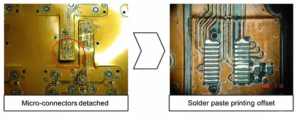
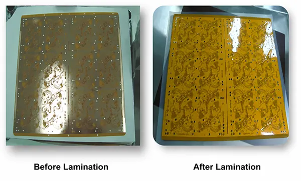

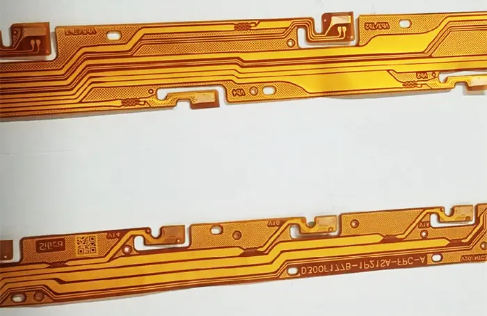
Flexible printed circuits are often treated as “smaller versions of rigid PCBs,” but this assumption is exactly where many reliability problems begin.
In real-world applications, flex PCB failures are rarely caused by electrical design flaws.
Instead, they originate from mechanical fatigue—cracks, delamination, and pad lifting—triggered by an incorrect choice of surface protection layer.
Across high-reliability industries such as automotive electronics, medical devices, and wearable systems, failure analysis reports consistently show a common pattern: when the protective layer cannot survive mechanical stress, the copper circuitry beneath it eventually fails.
The key decision behind these failures is simple but critical: coverlay vs flexible solder mask.
Why Flexible PCBs Need Two Different Protective Systems
Unlike rigid boards, flexible PCBs are designed to bend, twist, and in some cases continuously flex throughout their service life.
This means the outer protective layer is not just a chemical barrier—it becomes part of the mechanical structure.
Two dominant protection systems evolved to address this requirement:
- Coverlay, a laminated polyimide-based structural protection system
- Flexible solder mask, a liquid photoimageable (LPI) coating system used for precision patterning
Although both are designed to protect copper traces, they do so in fundamentally different ways.
Coverlay behaves like a mechanical shield integrated into the substrate, while flexible solder mask functions more like a precision dielectric coating applied on top of the circuit.
Industry standards such as IPC-2223 (Design Guide for Flexible Printed Boards) and IPC-6013 (Qualification and Performance Specification for Flexible Printed Boards) recognize this distinction by treating flex protection materials as application-dependent rather than interchangeable.
Coverlay Explained: The “Armor Layer” of Flex Circuits
What It Really Is
Coverlay is a composite material made of a polyimide film bonded with an adhesive layer, typically acrylic or epoxy-based.
It is laminated onto the flexible circuit under controlled heat and pressure, forming a permanent protective layer over exposed copper.
Typical construction parameters (industry range):
- Polyimide thickness: ~12.5–50 µm
- Adhesive layer: ~12.5–50 µm
- Total coverlay thickness: ~25–75 µm (application dependent)
This structure creates a continuous protective film rather than a surface coating, which is a key reason for its mechanical strength.
Why Engineers Trust It
Coverlay is widely used in high-reliability flexible electronics because it behaves as a stress-distributing layer rather than a brittle surface coating.
Its main engineering advantages include:
1. High fatigue resistance under repeated bending
The laminated polyimide structure distributes mechanical stress across a broader area, significantly improving bend cycle life compared to liquid coatings.
2. Strong environmental sealing
Coverlay provides a near-impermeable barrier against moisture, dust, and chemical exposure, which is critical in automotive and medical environments.
3. Thermal stability under reflow conditions
Polyimide-based systems maintain structural integrity during standard PCB assembly temperatures (typically up to ~260°C peak during reflow processes).
These properties make coverlay the preferred choice for dynamic flex regions where mechanical movement is continuous or repeated.
Where Coverlay Becomes a Limitation
Despite its mechanical strength, coverlay introduces manufacturing and design constraints:
- Larger feature tolerances are required due to mechanical cutting or laser-defined openings
- Less suitable for ultra-fine pitch SMT designs, where tight pad spacing is required
- Higher manufacturing complexity, including lamination pressure control and adhesive flow management
These constraints make coverlay less ideal in dense electronic assemblies, even though it performs exceptionally well mechanically.
Flexible Solder Mask Explained: The “Precision Coating Layer”
What It Really Is
Flexible solder mask is a modified version of traditional PCB solder resist, typically based on liquid photoimageable (LPI) epoxy or polymer systems.
It is applied as a liquid and then patterned using photolithography before being UV-cured into a solid protective layer.
Typical thickness range:
- ~8–20 µm depending on formulation and process control
Unlike coverlay, it does not form a laminated structural layer but instead acts as a thin functional coating.
Why It Wins in Precision Design
Flexible solder mask is primarily chosen for its patterning precision and fine feature capability.
Key advantages include:
1. Excellent fine-pitch control
Photolithographic processing allows extremely tight feature definition, making it suitable for dense SMT layouts.
2. High-resolution pad openings
Solder mask dams and apertures can be precisely controlled, which is essential for BGA, QFN, and other fine-pitch components.
3. Compatibility with rigid PCB manufacturing flows
Since it shares similarities with rigid PCB solder mask processes, it integrates well into standard high-volume PCB production lines.
Due to these characteristics, a flexible solder mask is often used in rigid-flex designs and static flex areas where mechanical stress is minimal.
Where Flexible Solder Mask Breaks Down (Literally)
Despite its precision advantages, flexible solder mask has a fundamental weakness: mechanical fatigue resistance.
Under repeated bending conditions, several failure modes are commonly observed:
- Micro-cracking along bend lines
- Delamination from copper surfaces
- Progressive degradation under cyclic stress
Industry studies and manufacturer reliability data consistently show that LPI-based coatings are significantly less durable than polyimide-based laminates in dynamic flex applications.
As a result, a flexible solder mask is generally not recommended for active bending zones.
Real Engineering Difference (Not What Most Articles Say)
Most comparisons between coverlay and solder mask focus on surface-level attributes like “thickness” or “cost.”
However, the real distinction is functional rather than cosmetic.
They serve fundamentally different engineering roles:
| Function Type | Coverlay | Flexible Solder Mask |
|---|---|---|
| Mechanical protection | High | Low |
| Electrical precision | Medium | High |
| Motion survival | Excellent | Limited |
| Manufacturing tolerance | Loose | Tight |
From an engineering systems perspective, this is the critical insight:
Coverlay is a structural material. Flexible solder mask is a patterning material.
They are not competing alternatives. They are designed for different failure modes.
Key Engineering Insight
A flexible PCB does not fail because it lacks protection. It fails because the wrong type of protection is applied to the wrong type of mechanical environment.
Coverlay is designed to survive motion by distributing stress. Flexible solder mask is designed to define electrical features with precision but assumes limited mechanical movement.
This distinction explains why high-reliability designs in automotive, aerospace, and medical electronics almost always combine both materials rather than choosing one over the other.
Where Engineers Get It Wrong: Failure Case Studies in Flex PCB Design
Even experienced PCB designers can underestimate how strongly mechanical protection influences flexible circuit reliability.
Unlike rigid boards, flex PCBs operate in a regime where mechanical fatigue dominates electrical failure mechanisms.
In practice, most field failures are not caused by schematic or routing errors—they are caused by subtle mismatches between material selection and real mechanical motion.
Where Engineers Get It Wrong (Failure Case Study Section)
Most Common Mistake: Using Solder Mask in Flexing Zones
One of the most frequent and costly design mistakes in flexible PCB development is the use of flexible solder mask in dynamic bending regions.
On paper, a flexible solder mask is often assumed to be “good enough” because it is labeled as flexible. However, in real mechanical conditions, it behaves very differently from laminated polyimide systems like coverlay.
Industry reliability observations (including IPC-2223 design guidance and multiple manufacturer failure analyses) consistently show that solder mask coatings are not optimized for cyclic strain environments.
The core issue is simple:
Solder mask is a coating. Coverlay is a structural layer.
When this distinction is ignored, the result is predictable failure behavior.
What Happens in Real Products
When solder mask is placed in bending zones or near repeated flexing regions, failures do not occur immediately. Instead, they develop gradually over mechanical cycles, often escaping early validation testing.
Micro-cracks after bending cycles
Under repeated deformation, the solder mask begins to form micro-fractures along high-strain areas. These cracks may not be visible during inspection but propagate over time, especially in tight bend radii.
Copper fatigue exposure
Once the protective coating fractures, copper traces become exposed to mechanical and environmental stress. This accelerates fatigue failure, especially in dynamic applications such as hinges, wearable devices, or moving sensor assemblies.
Field failure after passing lab tests
A critical industry concern is that many assemblies pass initial qualification testing (thermal cycling, basic flex testing), but fail in real-world use where bending frequency is higher and less controlled.
This mismatch between test conditions and real operating conditions is a well-documented challenge in flex reliability engineering.
Hidden Manufacturing Risks
Even when designers choose the correct material conceptually, manufacturing execution introduces additional risks that are often underestimated.
Adhesive flow in coverlay designs
Coverlay systems rely on adhesive layers that flow during lamination. If not properly controlled, adhesive squeeze-out can:
- contaminate fine-pitch pad areas
- reduce solderability
- create inconsistent insulation thickness
This is especially critical in high-density rigid-flex designs where spacing tolerances are tight.
Misalignment in pad openings
Coverlay openings are mechanically cut or laser-processed before lamination. Even small registration errors can result in:
- partially covered pads
- exposed copper edges
- uneven stress distribution during bending
Unlike solder mask, which is defined photolithographically, coverlay alignment has inherently larger mechanical tolerances.
Thickness stack-up errors
Because coverlay adds both polyimide and adhesive layers, stack-up calculations must account for:
- effective thickness reduction after lamination
- adhesive displacement into gaps
- impact on bend radius and ZIF connector fit
Ignoring these effects can lead to mechanical interference or unexpected stiffness in flex regions.
Bend Radius: The Invisible Rule That Decides Everything
In flexible PCB design, bend radius is not just a geometric constraint—it is the primary reliability determinant.
It defines how much strain the copper and protective layers experience during deformation, and it directly determines fatigue life.
According to IPC-2223 guidelines, bend radius is typically defined as a multiple of board thickness, with different thresholds for static and dynamic flexing conditions.
However, real-world performance is strongly influenced by the protective layer system used.
Why Bend Radius Is the Real Selection Driver
The choice between coverlay and solder mask is ultimately governed by mechanical strain tolerance.
- Tight bend radius → higher strain → requires structural protection (coverlay)
- Loose bend radius → lower strain → coating protection (solder mask may be acceptable)
This is why experienced flex designers often evaluate bend radius before selecting surface protection materials.
Dynamic vs Static Flex Behavior
Flexible circuits are generally classified into two mechanical modes:
Static flex:
The circuit is bent once or infrequently during installation and remains in a fixed shape. In these cases, solder mask may be acceptable in non-critical regions.
Dynamic flex:
The circuit undergoes repeated bending cycles throughout its lifetime.
This includes hinges, moving assemblies, and wearable devices. In these environments, coverlay becomes the dominant solution due to fatigue resistance.
The distinction is not theoretical—it directly determines failure rate over time.
How Protective Layer Choice Changes Mechanical Behavior
The selection of coverlay versus solder mask influences three key mechanical factors:
Fatigue life
Coverlay significantly increases cycle life by distributing strain across a polyimide film and adhesive system.
Solder mask, being a brittle coating, accumulates damage under repeated strain.
Stress distribution
Coverlay spreads mechanical stress across a laminated structure, reducing localized strain peaks.
Solder mask concentrates stress at the copper interface, increasing crack initiation probability.
Failure point location
With coverlay, failure (if it occurs) tends to shift away from copper traces toward laminate interfaces. With a solder mask, failure often begins directly at the copper surface due to coating fracture.
When to Use Coverlay vs Flexible Solder Mask (Decision Map)
A practical selection approach is not based on preference, but on operating conditions and risk tolerance.
Coverlay should be selected when:
- Dynamic bending is required during product life
- The product operates in harsh environments (humidity, vibration, thermal cycling)
- Long-term reliability is a primary design requirement
Flexible solder mask is more appropriate when:
- Fine-pitch SMT density is the dominant design constraint
- Cost optimization is critical for production scaling
- The flex section is static or experiences minimal movement
From an engineering standpoint, this is not a trade-off between “good and bad,” but between mechanical resilience and electrical precision.
Best Modern Approach: Hybrid Protection Strategy
Modern rigid-flex PCB design rarely relies on a single protective material. Instead, high-reliability systems increasingly adopt a hybrid protection architecture.
In this approach:
- Coverlay is applied to flex zones where mechanical strain occurs
- Flexible solder mask is used in rigid or high-density SMT areas
- Transition zones are carefully designed to avoid stress concentration
This hybrid method is widely used in automotive electronics, aerospace systems, and advanced medical devices because it aligns material properties with functional zones rather than forcing a single material to serve conflicting roles.
The key design challenge lies in managing the transition interface, where differences in thickness, adhesion behavior, and mechanical stiffness must be carefully controlled to avoid localized stress concentration.
Manufacturing Reality Check (What Designers Don’t See)
While design discussions often focus on electrical and mechanical theory, manufacturing introduces constraints that significantly influence final reliability.
Coverlay: Mechanical Processing Reality
Coverlay fabrication relies on:
- mechanical punching or laser cutting for openings
- lamination under heat and pressure
- adhesive flow control during bonding
This means:
- tolerances are larger
- alignment is more mechanically dependent
- yield is sensitive to registration accuracy
Flexible Solder Mask: Photolithographic Precision
Flexible solder mask production is based on:
- liquid coating application
- UV exposure and imaging
- chemical development processes
This allows:
- higher feature precision
- tighter pad definitions
- better control for dense SMT layouts
Alignment Tolerance Gap
A critical difference between the two systems is registration tolerance:
- Coverlay alignment: mechanically limited, typically looser tolerances
- Solder mask alignment: photolithographically controlled, significantly tighter tolerances
This gap directly impacts manufacturability and yield.
Yield Impact of Wrong Material Selection
When the wrong material is used in the wrong region, manufacturers typically observe:
- increased scrap rates due to misalignment
- higher rework costs in assembly
- reduced first-pass yield in high-density designs
- long-term reliability failures in field use
In many cases, these issues do not appear during prototyping but emerge during volume production or real-world operation.
Industry Standards That Quietly Control Your Design
Behind every successful flexible PCB design, there is usually a set of engineering rules that is not visible in the schematic—but strictly governs manufacturability and long-term reliability.
For flex circuits, these rules are largely defined by IPC standards, which act as the shared language between designers, fabricators, and assemblers.
Among these, three standards are especially important when deciding between coverlay and flexible solder mask.
IPC-2223: The Foundation of Flex and Rigid-Flex Design Rules
IPC-2223 is the primary design standard for flexible printed circuit boards and rigid-flex constructions.
It defines how mechanical motion, bend radius, stack-up configuration, and material selection interact in real-world applications.
For protective layers, IPC-2223 indirectly influences:
- Minimum bend radius based on material stack-up
- Copper strain limits in dynamic flex zones
- Recommended separation of rigid and flex regions
- Placement restrictions for vias, pads, and stiffeners
While it does not explicitly “choose” coverlay or solder mask, its mechanical strain guidelines effectively favor coverlay in dynamic flex regions, because laminated polyimide systems distribute stress more effectively than thin polymer coatings.
Industry reliability studies consistently align with IPC-2223 assumptions: repeated bending requires structural reinforcement, not just surface insulation.
IPC-4203: The Material Rulebook for Coverlay Systems
IPC-4203 defines the material requirements for flexible coverlay and bonding systems used in flexible printed circuits. This includes:
- Polyimide film characteristics
- Adhesive systems (acrylic, epoxy, or modified formulations)
- Thermal and mechanical performance requirements
- Electrical insulation properties
One of the most important implications of IPC-4203 is that coverlay is treated as a structural dielectric system, not just a coating. This distinction explains why coverlay:
- Requires lamination under controlled pressure and temperature
- Has defined adhesive flow and thickness constraints
- Must meet mechanical endurance expectations under flex cycling
In practical terms, IPC-4203 formalizes what engineers observe in the field: coverlay is designed for mechanical survival, not just electrical protection.
IPC-6013: Performance Expectations Under Real Operating Conditions
IPC-6013 defines qualification and performance requirements for flexible and rigid-flex PCBs. It focuses on how boards behave after fabrication, not just how they are built.
Key reliability expectations include:
- Resistance to thermal cycling
- Adhesion integrity under mechanical stress
- Conductor integrity in flex conditions
- Environmental durability (humidity, chemicals, vibration)
From a protective-layer perspective, IPC-6013 reinforces a critical principle:
The reliability of a flex PCB is determined more by mechanical stack-up than by electrical design.
This is why designs using flexible solder mask in dynamic bend zones often struggle to meet long-term IPC-6013 reliability expectations, while coverlay-based structures consistently perform better under qualification testing.
Future Trend: Are We Moving Beyond This Choice?
Although coverlay and flexible solder mask are currently the dominant technologies, flex PCB materials are evolving rapidly.
The industry is actively exploring new approaches that aim to reduce the trade-off between mechanical strength and patterning precision.
Advanced Adhesive-Less Coverlay Systems
Traditional coverlay relies on adhesive layers that introduce:
- Thickness variation
- Adhesive squeeze-out risk
- Lamination stress concentration
New adhesive-less systems aim to eliminate this interface entirely by using:
- Modified polyimide chemistry
- Direct bonding techniques
- Plasma-activated surfaces
The goal is to improve dimensional stability and reduce mechanical fatigue points, especially in high-cycle bending applications.
Ultra-Thin Flexible Solder Masks
Flexible solder mask technology is also evolving toward thinner, more compliant coatings. Advanced formulations aim to:
- Increase elongation before crack formation
- Improve adhesion to polyimide substrates
- Reduce modulus mismatch with copper surfaces
However, even with improved flexibility, these materials still face a fundamental limitation: they remain coating-based systems rather than structural laminates.
This means their fatigue performance will likely improve, but not fully match the coverlay in high-cycle bending environments.
Hybrid Nano-Coatings
One of the more experimental directions is the development of nano-engineered protective coatings. These materials combine:
- Thin-film dielectric layers
- Flexible polymer matrices
- Reinforced nano-fillers for crack resistance
The objective is to create a protective layer that behaves like a coating in precision but like a laminate in durability. If successful, this could significantly reduce the gap between coverlay and solder mask performance.
AI-Driven Flex Reliability Prediction
Another emerging trend is not material-based but design-based: using AI and simulation models to predict flex failure before fabrication.
These systems analyze:
- Bend radius and strain distribution
- Material stack-up interactions
- Copper routing patterns in flex zones
- Thermal and mechanical cycling profiles
By predicting failure points early, engineers can optimize where coverlay or solder mask should be applied—potentially reducing overdesign and improving yield without changing materials.
This represents a shift from material selection-driven design to data-driven reliability engineering.
Conclusion: The Simple Rule That Prevents Most Failures
Despite all the complexity in materials, standards, and manufacturing processes, flex PCB reliability ultimately comes down to one principle:
Mechanical motion determines material choice—not the other way around.
A simplified but highly effective engineering rule can be stated as:
- If the PCB moves → use coverlay
- If the PCB stays precise → use solder mask
- If both exist → combine them correctly in separate zones
This zoning approach is the foundation of modern rigid-flex design.
It reflects how high-reliability industries such as automotive, aerospace, and medical electronics actually achieve long product lifetimes—not by selecting a “better” material, but by placing the right material in the right mechanical environment.
The most successful flex PCB designs are not those that push a single material to its limits, but those that respect the fundamental difference between structural protection (coverlay) and precision patterning (solder mask).
When this principle is followed early in the design stage, most downstream issues—cracking, delamination, pad lifting, and unexpected field failures—are effectively eliminated before they ever reach production.





