
Flexible PCB SMT Process: Complete Guide to Flexible PCB SMT Assembly and FPC Reflow
Therefore, the Flexible PCB SMT process is the method used to solder surface-mount components onto a polyimide or polyester flex circuit. Additionally, a bare flex panel cannot support printing or placement by itself, so it is fixed to a carrier first. Meanwhile, then it is printed, placed and reflowed. For example, this guide covers each step of flexible PCB SMT assembly, including the FPC reflow process.
What Is Flexible PCB SMT Assembly?
In addition, flexible PCB SMT assembly is the surface-mount build of a flexible printed circuit, often shortened to FPCA. As a result, the substrate is a polyimide or polyester film. In practice, according to JIS C5017, single-sided and double-sided flexible boards are made by laminating copper foil onto a PET or PI base, then forming circuits on one or both sides.
Next, miniaturization drives this work. Consequently, space inside consumer products is tight, so a large share of SMDs sit on flex boards. Moreover, common examples include calculators, mobile phones, digital cameras and camcorders. In particular, the same process serves MP3 and MP4 players, portable CD players, VCD and DVD players, phone batteries, digital walkie-talkies, and medical, automotive, aerospace and military hardware.
However, before SMT, every panel passes through flexible pcb material preparation, PCB Etching and PCB Lamination. Therefore, each step affects how flat the panel arrives at the printer.
Features of Flexible PCB That Affect Assembly
| Advantage | Disadvantage |
|---|---|
| Lightweight, compact and thin | Long process chain, strict environment control, high cost |
| Bends, folds and moves freely in 3D space | Higher scrap rate |
| Greater design freedom for 3D routing | Lower mechanical strength |
| Excellent heat dissipation | Inspection is harder than on rigid PCBs |
| Higher wiring density | Needs production fixtures and strong fixture design skills |
Additionally, these traits shape the assembly plan. For example, low mechanical strength means the panel needs support at every station, not just at the printer. In addition, inspection is harder, so the test plan must be tighter than on a rigid board. Meanwhile, the Flexible PCB Process Guide covers the fabrication side that creates these traits.
Carrier and Fixture Attachment: Key Process Points
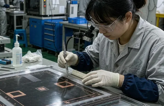
For example, positioning decides yield. A flex panel lacks the stiffness needed for printing, placement and reflow. Therefore, the panel is clamped onto a carrier board that carries it through every station.
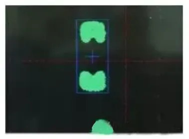
Solder paste mark point technology
The sequence is consistent: pre-treatment, clamping, printing, component placement, reflow soldering, testing, inspection and panel separation. Each step depends on the fixture before it.
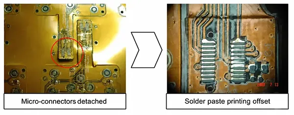
Fixture design is the hard part. The carrier must hold the panel flat, locate it accurately and release it without stress. Also, engineers need strong fixture design skills, because a weak carrier shows up later as placement offset or solder defects.
High-volume work can run on roll-to-roll (RTR) lines. Large flex makers began building RTR lines in the 1980s. Early yields were very low, because the process technology of that era was not mature yet.
Stencil Printing and Pick-and-Place on Flex Panels
Printing sets the paste volume for the whole run. The stencil must sit flat against the panel, so the carrier has to give a hard, even surface beneath the print area. Any gap lets paste bleed and produces uneven deposits.
Placement adds two more risks: pressure and support. A flex panel bends under the nozzle force, so the machine needs a flat backing at each placement position. Vacuum and clamp features hold the panel down. Without them, parts shift or tombstone during reflow.
Warpage matters here too. A carrier that is slightly bowed will produce offset placements at one end of the panel. Therefore, flatness is checked before the run starts, not after.
FPC Reflow Process: Carrier Support, Heat and Warpage Control
The FPC reflow process is where carrier quality shows. Panel and carrier travel through the oven as one unit. The carrier controls heat spread and keeps the panel flat while the solder is liquid.
Three factors drive the profile: panel thickness, copper distribution and component mix. A thin flex panel heats quickly, so an aggressive profile can overheat small parts near heavy copper. For example, a ground plane pulls heat away and can leave cold joints at the far edge.
Pre-treatment comes first. Panels are conditioned before reflow to remove moisture. After that, the profile is set on the real panel-and-carrier stack, not on a bare test coupon.
Cooling deserves the same attention. Fast cooling on a thin substrate adds stress to the joints. A gentler ramp protects both the solder and the flex material.
Testing, Inspection and Panel Separation
After reflow, the panel moves to inspection and testing. Optical inspection follows the print and placement checks. Electrical testing then confirms continuity and isolation. Functional testing comes last for assemblies that carry active parts.
Panel separation closes the run. Singulation must not stress the flex tail or the joints beside the cut line. A dull blade or a rough fixture shows up as a cracked trace weeks later in the field.
Data from these stations feeds back to the front of the line. For example, a repeat paste defect usually points to a carrier or stencil problem, not to the printer. A Flexible PCB Manufacturer that controls both fabrication and assembly can close that loop faster.
Why Flexible PCB SMT Is Different from Standard SMT
A rigid board supports itself. However, a flex board does not. That single fact explains most of the gap between flexible PCB SMT assembly and standard SMT.
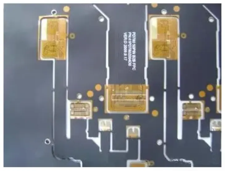
Rigid SMT uses the board as the transport medium. Flex SMT uses a carrier, and that carrier becomes part of the process window. Setup time, fixture cost and operator handling all rise as a result.
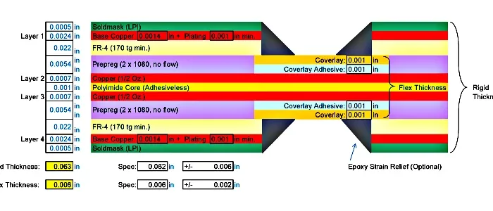
Rigid-flex boards sit between the two cases. The rigid sections can carry standard tooling, while the flex sections still need support. Therefore, the fixture plan follows the flex areas, not the whole panel.
These rules matter most in high-reliability work. Medical devices, automotive modules and aerospace hardware all use flexible PCB SMT assembly, where one lifted joint becomes a field failure. Gekun builds Flexible Circuits for High-Reliability Flexible Circuits for High-End Applications programs, and the assembly plan is agreed before tooling starts.
FAQ
What is the difference between flexible PCB SMT assembly and standard SMT?
Standard SMT uses the rigid board as its own support and transport medium. Flexible PCB SMT assembly adds a carrier, because a bare flex panel cannot be printed, placed or reflowed without backing. That carrier adds fixture design, setup time and handling cost, yet it is the only reliable way to keep the panel flat.
Why does an FPC reflow process need a carrier board?
The FPC reflow process needs a carrier for three reasons: transport, flatness and heat control. The carrier moves the thin panel through the oven, holds it flat while the solder is liquid, and spreads heat so thin areas do not overheat. Without it, warpage and offset joints appear across the panel.
Which products use flexible PCB SMT assembly?
Common products include calculators, mobile phones, digital cameras, camcorders, MP3 and MP4 players, portable CD players, VCD and DVD players, phone batteries and digital walkie-talkies. The same assembly is used in medical, automotive, aerospace and military hardware. For panel, tooling and tolerance questions, see the PCB Manufacturing FAQ.
Related Posts
- Flexible PCB & Rigid Flex PCB Etching Process — Related article
- Flexible PCB Material Preparation: Cutting and Cleaning Process — Related article
- Flexible PCB Process Guide — Related article
- PCB Lamination Process | Rigid & Flexible PCB Manufacturing Guide — Related article
- PI Protective Film Process for Rigid-Flex PCBs: Reducing Flexible-Area Cosmetic Defects – GekunFlex — Related article