
Rigid-Flex PCB Drilling: New Technologies to Reduce Burrs and Improve Yield
Rigid-Flex PCB Drilling creates burrs because the flex zone sits lower than the rigid zone. The drill exits into a gap between the board and the backing plate, so soft material tears instead of cutting cleanly. This guide explains the burr mechanism, places drilling inside the full process flow, compares mechanical and laser drilling, and shows which burr reduction methods keep burrs small and yield high.
Why Burrs Form in Rigid-Flex PCB Drilling
A rigid-flex board is a composite. Flex circuits and rigid boards are laminated together, so the flex regions stay thinner than the rigid regions. The board surface is therefore not flat. Cushioning materials used in lamination add compression, which makes the height difference larger.
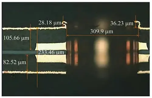
The difference in elevation results in large burrs
The thinner areas form recessed zones. During drilling, a gap remains between the backing plate and the flex region. When the drill exits, it pushes material into that gap, and a rigid-flex PCB drilling burr opens up at the hole edge. When the height difference is large, parameter tuning alone cannot close the gap. Burrs then exceed 30 µm.
Burr Formation Mechanism: Polyimide, Acrylic Adhesive and Copper
Polyimide and acrylic adhesive are soft and have low thermal conductivity. At the drill point they soften, smear and sometimes carbonize before the cutting edge clears the exit. The copper foil can fold into a lip, while the dielectric tears into a fringe. If adhesive is squeezed into the hole wall, it can bake into a tenacious smear that is harder to remove than a metal burr.
Mechanical drilling and laser drilling do not produce the same burr morphology. Mechanical drilling produces folded copper, torn polyimide, adhesive smear and occasional coverlay delamination. The burr is mechanical and often attached at the exit edge. Laser drilling produces little folded metal, but it can leave recast layer, carbonized residue, dross and a heat-affected zone. If laser energy is too low, incomplete ablation leaves residue; if energy is too high, charring and micro-cracks appear. The fix is different: mechanical burrs need support and sharp tools, while laser burrs need energy control, overlap and plasma cleanup.
Where Drilling Fits in the Rigid-Flex Process Flow
Drilling is not an isolated step. The flow runs material preparation, lamination, drilling, desmear or plasma, plating and etching. Each upstream and downstream step changes the burr result.
Upstream, material preparation sets the coverlay adhesive type, copper thickness and moisture content. Lamination sets the height difference between rigid and flex zones and controls how much adhesive flows toward the drill area. A large height difference or excess adhesive squeeze-out leaves a gap or a soft pocket at the exit, so the drill tears material instead of cutting it.
Downstream, desmear or plasma removes smear from the hole barrel. If smear is not removed, plating adhesion drops and voids form; if plasma is over-applied, the hole edge can undercut. Plating then follows the exit edge. A burr can shadow plating, create a void or bridge at the surface. Etching also matters because copper thickness changes the burr profile; PCB Etching explains that link. In short, burr control starts before drilling and is confirmed after plating.
Hole and Slot Applications in Rigid-Flex Drilling
Rigid-flex drilling covers more than round through-holes. Through-holes connect rigid and flex layers. Microvias are common in the rigid sections. Slots are used for bend relief, coverlay windows, tooling and sometimes for shielding. Backdrilled holes appear in bookbinder structures where depth control is critical.
Slots need special attention. A slot edge in a bend area acts as a crack starter if a burr or recast lip remains. Coverlay window slots must be aligned with the drill pattern so adhesive does not bleed into the opening. Tooling holes can tolerate a different burr limit than signal vias, so define the acceptance band by feature type, not by one plant-wide rule.
Hole Size Limits, Aspect Ratio and Positioning Tolerances
Mechanical drilling is practical for through-holes across rigid and flex zones, but small holes increase burr sensitivity. Laser drilling reaches smaller diameters, yet the dielectric and copper thickness limit the usable energy window. The table below gives a working capability comparison for burr-controlled rigid-flex drilling.
| Capability | Mechanical micro-drill | UV/ps laser drill | Drilling note |
|---|---|---|---|
| Hole diameter | 0.10–0.30 mm typical; 0.075 mm with special tooling | 25–75 µm typical; smaller in thin dielectric | Smaller holes need tighter support and parameter control |
| Aspect ratio | 8:1–10:1 in rigid zones; lower in flex | 1:1–3:1 for microvias | High aspect ratio traps debris and heat |
| Depth tolerance | ±0.05 mm | ±0.01–0.02 mm | Backdrill needs closed-loop depth control |
| Backdrill depth capability | 0.005 in (127 µm) baseline; 0.002 in (51 µm) with advanced depth control | Not typical for backdrill | Bookbinder structures depend on depth control |
| Positioning accuracy | ±25 µm | ±10–15 µm | Affects slot and coverlay window alignment |
| Feature size tolerance | ±25–50 µm | ±15–25 µm | Include burr allowance in window design |
| Bookbinder / multi-leg structures | Depth-controlled backdrill; support each leg | Laser for microvias in rigid legs | Uneven support raises exit burr |
Positioning accuracy matters because a burr that grows into a coverlay window or a bend-relief slot is worse than a burr on a non-functional edge. Define the datum, the drill-to-coverlay tolerance and the burr allowance together.
Mechanical Micro-Drilling vs Laser Drilling: Trade-offs
The choice is not only about burr height. It is a trade-off among hole size, aspect ratio, taper, heat damage, throughput and cost.
| Point | Mechanical micro-drill | UV/ps laser drill |
|---|---|---|
| Hole size lower limit | About 0.10 mm typical; 0.075 mm with special tooling | 25–75 µm typical |
| Aspect ratio | 8:1–10:1 in rigid zones | 1:1–3:1 for microvias |
| Taper | Low to moderate; depends on bit wear | Can be noticeable if focus and passes are not controlled |
| Heat-affected zone | Small mechanical zone; friction heat can smear adhesive | Recast and carbonized layer must be removed |
| Burr form | Folded copper, torn polyimide, adhesive smear | Dross, recast, little folded metal |
| Support needed | Backing plate and shim that reach the recessed flex zone | Focus, energy and assist gas control |
| Tool wear | Drill bit life must be tracked and retired on schedule | Power drift must be calibrated |
| Throughput and cost | Lower capital cost; bit wear and support tooling add cost | Higher capital cost; fast for small holes and no bit wear |
| Best fit | Through-holes across rigid and flex zones | Fine features where a bit cannot support the exit side |
New Technologies to Reduce Burrs in Rigid-Flex Drilling
The newer direction is to remove the force that tears soft material and to clean the edge without creating a new defect. Support-first tooling, cold laser ablation, plasma cleanup, coverlay window design and inline inspection work together.
Support-First Tooling: Dry Film and Laminated Aids
Support-first tooling presses the flex zone flat against the backing plate, so the drill exits into solid material. Riveted aluminum sheets or epoxy boards riveted to aluminum sheets support the exit side and bring burrs to 10–20 µm. Dry film laminated on both surfaces before mechanical drilling goes further: the film is exposed in the drill areas and developed, so only exposed film stays. This support layer limits burrs to 2–6 µm and can replace covers and shims. The trade-off is extra lamination, exposure and development steps, but the grinding step may be removed.
Picosecond and UV Laser Cold Ablation
Picosecond UV laser drilling at 355 nm removes polyimide and adhesive with short pulses, so the thermal load is lower than with long-pulse lasers. The practical window uses energy density above the ablation threshold but below charring, multiple passes, controlled overlap and assist gas to clear debris. Multi-pulse parameters reduce the heat-affected zone and limit recast. Focus position must be set for the actual surface height, because the rigid-flex surface is not flat. If the focus drifts, the exit edge becomes tapered or carbonized.
Plasma Desmear and Deburring
Plasma treatment after drilling removes smear from the hole barrel and can clean organic fuzz at the exit. It improves plating adhesion and helps the hole stay round. Batch plasma and inline plasma are both used; the gas chemistry and cycle time must match the polyimide and adhesive. Over-treatment can undercut the hole edge, so plasma is a controlled cleanup step, not a substitute for good drilling support.
Coverlay Window and Adhesive Flow Control
Coverlay windows should be designed with the drill pattern and the adhesive flow in mind. A window that is too tight lets adhesive squeeze into the hole; a window that is too wide exposes the bend area. Low-flow adhesive, proper lamination pressure and a clean coverlay opening reduce the soft pocket at the exit. Laser cutting of coverlay windows gives a clean edge and better registration than mechanical punching on small features.
Rigid-Flex Transition and Bend-Area Drilling Risks
The rigid-flex transition is the highest-risk zone. Coverlay, adhesive and copper meet at the transition, and the drill can exit into a stepped surface. Risks include coverlay delamination, adhesive smear, burr at the bend-relief slot and cracking after bending. Keep drill edges outside the bend radius plus a margin, use rounded slot ends instead of sharp corners, and avoid placing microvias directly on the neutral axis transition. In bookbinder structures, each flex leg needs its own support so the drill does not push material into an unsupported gap.
Parameter Windows and Burr Height Acceptance
A parameter window is only useful if it is tied to a measured burr limit. The following window is a starting point for UV/ps laser drilling of polyimide and acrylic adhesive; it must be tuned to the actual stack-up.
| Parameter | Typical UV/ps laser window | Burr-control effect |
|---|---|---|
| Pulse energy | 5–50 µJ | Too low leaves residue; too high chars the edge |
| Frequency | 50–200 kHz | Sets overlap and heat input |
| Passes | 2–6 | Multiple passes reduce thermal load per pass |
| Focus position | Top surface ±50 µm | Controls taper and exit dross |
| Assist gas | N2 at 0.2–0.5 MPa | Removes debris and limits oxidation |
| Energy density | 1–5 J/cm² | Above ablation threshold, below charring |
| Spot overlap | 50–80% | Too low leaves scallops; too high adds heat |
For mechanical drilling, the equivalent window is spindle speed, feed per revolution, bit life and backing support. Retire bits on schedule instead of running them to failure.
Burr height should be measured as maximum height above the surface, burr length along the edge and adhesive smear area. Define an internal limit by feature type. A general limit may be ≤25 µm, while a high-reliability or bend-area limit may be ≤12.5 µm. IPC-6013 acceptance is tied to the class and to whether the burr bridges conductors, obstructs plating or cracks in bending; use the standard plus the customer drawing, not a single universal number. After plasma, recast layer should also be checked, for example ≤5 µm on critical microvias.
Equipment and Process Capability for Burr-Controlled Drilling
The technology is feasible because the equipment exists. Mechanical CNC drilling with automatic tool change and depth control handles through-holes and backdrill. UV and picosecond laser drill rigs handle microvias and fine slots. Dry-film laminators provide support-first tooling. Plasma desmear systems clean the hole barrel. Deburring and grinding lines remain available for conventional flows. AOI and cross-section labs close the loop. The process capability comes from combining these tools, not from one machine alone.
DFM and Factory Processing Challenges
Start with the stack-up. Keep the height difference between rigid and flex zones as small as the design allows, and define where the recessed zones sit. Choose a backing plate and shim that reach the flex surface, not just the rigid frame. Add dry film support on both sides before mechanical drilling when burrs must stay below 10 µm. At the rigid-flex transition, keep drill edges away from the bend zone and use rounded slots.
Factory challenges are real: dry film must register to the drill pattern, the backing plate must contact the recessed flex area, laser focus must follow a non-flat surface, adhesive outgassing can contaminate optics, and bookbinder legs need independent support. Drill parameters must be set per material, and bit life must be tracked. The bond interface and coverlay bonding strength affect how the exit edge behaves. Etching also changes the copper burr profile, so copper thickness and etch factor belong in the DFM review. Finally, plan plasma cleanup and burr measurement before the build starts.
Yield Impact: Failure Modes and Before/After Data
Burrs cause yield loss through shorts, plating voids, delamination at the coverlay and bend cracks. In a representative 6-layer rigid-flex build with 0.15 mm holes, 25 µm polyimide and acrylic coverlay, the baseline burr was above 30 µm and scrap was about 9%. Plating voids accounted for roughly 4%, shorts for about 3%, coverlay delamination for about 1.5% and bend cracks for the remainder.
After moving to dry-film support, plasma cleanup and laser drilling for the microvias, burr height fell to 3–8 µm and scrap dropped to about 2.5%. Plating voids fell to about 1%, shorts to below 1% and delamination to under 0.5%. The exact numbers depend on the stack-up, but the pattern is consistent: support-first drilling removes the largest burr source, and plasma protects the plating interface.
Inspection and Verification Methods
Burr control only counts when it is measured. Use cross-section metallography to inspect the exit edge and measure burr height. SEM is useful for recast, carbonized residue and adhesive smear. Laser confocal or stylus profiling can measure burr height on coupons. AOI after drilling catches folded metal and surface dross; AOI after plating catches voids and bridges. Adhesion and thermal cycling tests, including IST where required, confirm that the cleaned hole survives assembly and bending. Keep a first-article cross-section and a periodic coupon check in the control plan.
Cost Drivers in Rigid-Flex PCB Drilling
Support tooling adds dry film, lamination, exposure and development cost, but it can remove grinding and reduce scrap. Laser drilling has higher capital cost but no bit wear and reaches small holes that mechanical drilling cannot support. Backdrill depth control for bookbinder structures adds test and equipment time. Plasma adds a step but protects plating yield. The lowest-cost flow is not always the one with the fewest steps; it is the one that holds burrs inside the acceptance band with the least scrap.
Key Takeaways
- Rigid-flex drilling burrs come from the exit gap at the recessed flex zone and from soft polyimide and acrylic adhesive that tear or smear.
- Mechanical and laser drilling create different burr morphology: folded metal and smear versus recast, dross and heat-affected zone.
- Support-first tooling with dry film can hold burrs at 2–6 µm; laminated aids typically reach 10–20 µm; unsupported large height differences often exceed 30 µm.
- Drilling sits between lamination and plating, so stack-up, desmear and etching all change the burr result.
- Capability planning should cover hole size, aspect ratio, positioning tolerance, backdrill depth from 0.005 in to 0.002 in and bookbinder structures.
- Use a measured burr limit tied to IPC-6013 class and the customer drawing, and verify with cross-section, SEM and AOI.
burr reduction rigid-flex drilling
burr reduction rigid-flex drilling is addressed in material choice, process control, and inspection, supporting the primary topic without changing the page focus.
FAQ
What causes burrs in rigid-flex PCB drilling?
Burrs come from the height difference between the rigid and flex zones. The flex zone is thinner and forms a recessed area, so a gap remains between the board and the backing plate. When the drill exits, soft polyimide and adhesive tear or smear into that gap and form a burr at the hole opening. Adhesive can also carbonize and create a tenacious smear.
How small can burrs be after burr reduction in rigid-flex drilling?
With lamination aids such as riveted aluminum and epoxy sheets, burrs fall to 10–20 µm. With dry film laminated as a support layer before drilling, burrs fall to 2–6 µm. Without support, a large height difference often leaves burrs above 30 µm.
Does laser drilling remove burrs completely?
No. Laser drilling removes the cutting force that tears the flex material, so the mechanical exit burr is much smaller. However, the process still needs matching to the dielectric and copper thickness. Recast, carbonized residue, dross and heat-affected zone must be checked, and plasma cleanup plus inspection remain part of the flow.
How do mechanical and laser burrs differ in rigid-flex drilling?
Mechanical burrs are mainly folded copper, torn polyimide and adhesive smear. Laser burrs are mainly recast, carbonized residue and dross, with little folded metal. That is why mechanical drilling relies on backing support and sharp bits, while laser drilling relies on energy density, overlap, focus and plasma cleanup.
How is burr height measured and accepted?
Measure maximum burr height, burr length and smear area on a cross-section or coupon. Set an internal limit by feature type, then check it against IPC-6013 class and the customer drawing. A general limit may be ≤25 µm, while bend-area or high-reliability features may need ≤12.5 µm. Reject burrs that bridge conductors, obstruct plating or crack in bending.
What DFM rules reduce burr risk at the rigid-flex transition?
Keep drill edges outside the bend radius plus a margin, use rounded slot ends, avoid microvias on the transition neutral axis, and design coverlay windows that control adhesive flow. In bookbinder structures, support each flex leg independently and control backdrill depth.
Can plasma replace deburring in rigid-flex drilling?
Plasma is a cleanup step, not a complete replacement for good drilling support. It removes smear and organic fuzz and improves plating adhesion, but it cannot close a large exit gap or repair a folded copper burr. Use plasma with support-first tooling and AOI.
What yield improvement can support-first drilling deliver?
In a representative build, moving from unsupported drilling above 30 µm burr to dry-film support and plasma reduced scrap from about 9% to about 2.5%. Plating voids and shorts fell most. The exact gain depends on stack-up, hole size and inspection limits.
What are the main factory challenges in burr-controlled rigid-flex drilling?
Dry-film registration, backing-plate contact on recessed flex zones, laser focus on a non-flat surface, adhesive outgassing, bookbinder depth control and reliable burr measurement are the main challenges. Each one needs a process control plan, not just a drill parameter change.
Related Posts
- Coverlay Bonding Strength Optimization in Rigid-Flex PCB — Related article
- FCCL vs. Rigid Copper Clad Laminate: Key Differences — Related article
- Flexible PCB & Rigid Flex PCB Etching Process — Related article
- High-Frequency Rigid-Flex PCB Manufacturing — Related article
- Improve PCB Micro-Drill Performance on Flex Boards — Related article