
Improve PCB Micro-Drill Performance on Flex Boards
Improve PCB Micro-Drill Performance on Flex Boards
Direct answer: Flexible PCB micro-drilling requires a stack-specific approach. The most effective way to improve hole quality and micro-drill performance is to stabilize the flexible stack with rigid entry and backer materials, select drill geometry suited to polyimide and adhesive layers, and carefully control feed, speed, chip load, peck depth, and hit count. This limits the main flex-circuit drilling defects: resin smear, adhesive smear, copper burrs, nailheading, hole-wall roughness, and delamination.
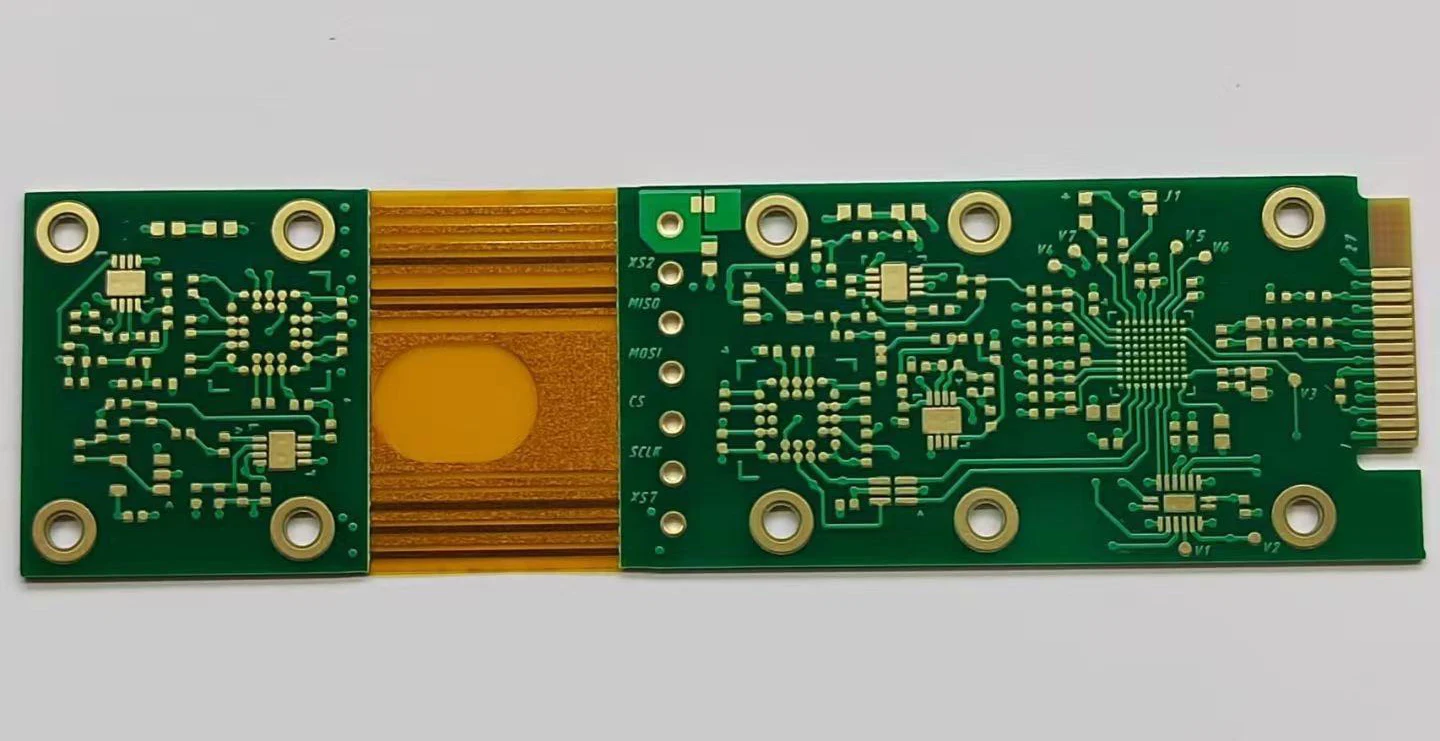
Flexible printed circuit boards, or FPCBs, are manufactured using polyimide or polyester film as the substrate. These materials are bonded with flexible copper-clad laminate and insulating layers through adhesive lamination. The resulting circuit can bend, roll, and fold, which makes it valuable for compact electronic assemblies that require three-dimensional interconnection. However, the same material properties that give flex circuits their advantages also make micro-drilling more sensitive than drilling rigid FR-4.
This guide consolidates practical recommendations for micro-drilling flexible PCB materials and improving micro-drill performance on flex boards. Use it as a reference when setting up drilling processes, selecting tools, or troubleshooting hole-wall defects.
[Read more: Flexible PCBs: Structure, Materials, and Selection Guide]
Why Flexible PCB Drilling Is Different
Flex PCB drilling differs from rigid PCB drilling because the stack is not uniformly hard. A typical flex drilling stack includes:
- Polyimide or polyester base film
- Flexible copper-clad laminate, which is thin copper bonded to polyimide or polyester
- Adhesive layers between conductive and insulating layers
- Coverlay or flexible solder mask in some designs
Polyimide is abrasive and can accelerate tool wear. Adhesive layers are soft and thermally sensitive; they can melt, smear, or leave residue on the hole wall. The copper in flexible copper-clad laminate is thin and ductile, so it tends to deform into burrs or nailheading at the hole entry and exit. Because the material is flexible, it also moves more under drill pressure unless it is properly supported.
These differences mean that copying a rigid FR-4 drilling recipe to a flex stack usually produces poor results. The correct process starts with recognizing that flexible PCB micro-drilling is a material-stability problem as much as a hole-formation problem.
[Read more: FCCL vs. rigid copper clad laminate]
—
Common Hole Quality Defects in Flexible PCB Micro-Drilling
Defects in flex-circuit micro-drilling tend to concentrate at the material interfaces. The most common are:
Smear and adhesive residue
During drilling, frictional heat can soften the adhesive layers. The softened adhesive can smear across the hole wall and cover the exposed copper inner layers. This residue prevents reliable through-hole interconnection and can require aggressive desmearing processes that damage polyimide. The goal is to reduce heat generation while maintaining drill sharpness.
Burrs and nailheading
Thin flexible copper is more prone to burr formation than thick rigid copper. At the drill entry, the copper can be pushed outward and form a burr. At the exit, the copper can deform into a nailhead shape. Both defects are influenced by drill sharpness, feed rate, and whether the stack is supported by a clean, rigid entry and backer board.
Hole-wall roughness and delamination
A rough hole wall in polyimide or adhesive layers can indicate worn tool geometry, excessive heat, or vibration. In flexible stacks, roughness can also appear as micro-delamination between copper, adhesive, and polyimide. Once interfaces separate, hole-wall quality degrades quickly and the panel may fail electrical test.
Stack Preparation and Tooling for Better Hole Quality
Before changing drill parameters, optimize the stack. This is often the fastest way to improve results in flexible PCB micro-drilling.
Use rigid entry and backer boards
Entry boards protect the top copper surface and help reduce burrs. Backer boards support the flexible stack at drill exit and limit nailheading. For flex materials, the entry and backer should be flat, clean, and rigid enough to resist stack movement. Replace them before they become worn or loaded with drilled debris.
Keep the stack flat and tight
Flexible panels can move, buckle, or lift during drilling. Use proper clamping, vacuum, and pressure foot settings to hold the stack against the machine table. If the stack oscillates under the drill, the result is inconsistent depth control, rough walls, and early tool breakage.
Align pins and tooling holes
Registration is critical in flexible PCB drilling because the material can expand or contract with temperature and tension. Use tooling holes and pinning to keep layers aligned. Misaligned layers create offset holes and uneven material removal, which worsens burrs and smear.
—
Micro-Drill Selection for Polyimide and FCCL
Tool selection directly affects hole quality in flexible PCB micro-drilling. The drill must cut abrasive polyimide cleanly, shear thin copper without excessive burring, and avoid overheating adhesive layers.
Drill geometry and flute design
For flex stacks, consider drills with geometry that promotes clean chip evacuation and low cutting force. Sharp cutting edges are essential. A dull drill rubs instead of cuts, generating heat that smears adhesive and hardens polyimide residue.
Tool material and coating considerations
Micro-drills for flexible PCB drilling often use fine-grain carbide. Coatings may help reduce friction and adhesion, but they should be selected for the specific stack. The priority is not maximum hardness alone; the tool must remain sharp enough to cut copper cleanly while resisting abrasive wear from polyimide.
Diameter and aspect ratio
Small hole diameters and high aspect ratios are common in flexible PCB micro-drilling. As the drill gets smaller, rigidity decreases and the risk of deflection, vibration, and breakage increases. Use the shortest practical tool length and the largest practical web thickness consistent with the hole size.
FPCB Micro-HOLE Drilling Optimization and Test Results
(1) Reducing the drill’s helix angle
This optimization further increases the internal flute space based on previous designs to reduce heat generation during drilling, resulting in improved hole wall quality.
(2) Reducing the drill’s ligament width
Ligament width directly impacts hole wall roughness. A wider ligament increases the contact area between the drill and hole wall during drilling, leading to greater heat generation and directly compromising hole wall quality. Reducing the ligament width enhances hole wall quality.
Optimized test data (Tables 2, 3, 4, and 5) demonstrate improved hole wall quality and enhanced positional accuracy.

Table 2 Hole Location Accuracy Statistics

Table 3 Hole Wall Precision Statistics
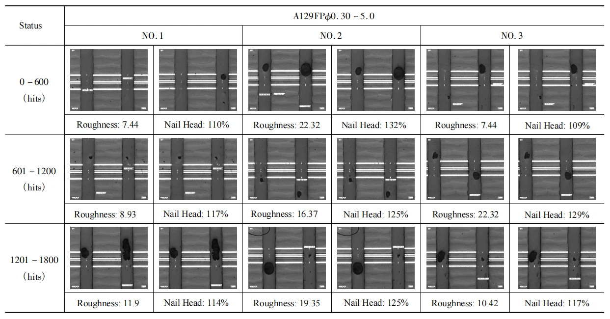
Table 4 A129FP⌀ 0.30–5.0 Hole Wall Precision
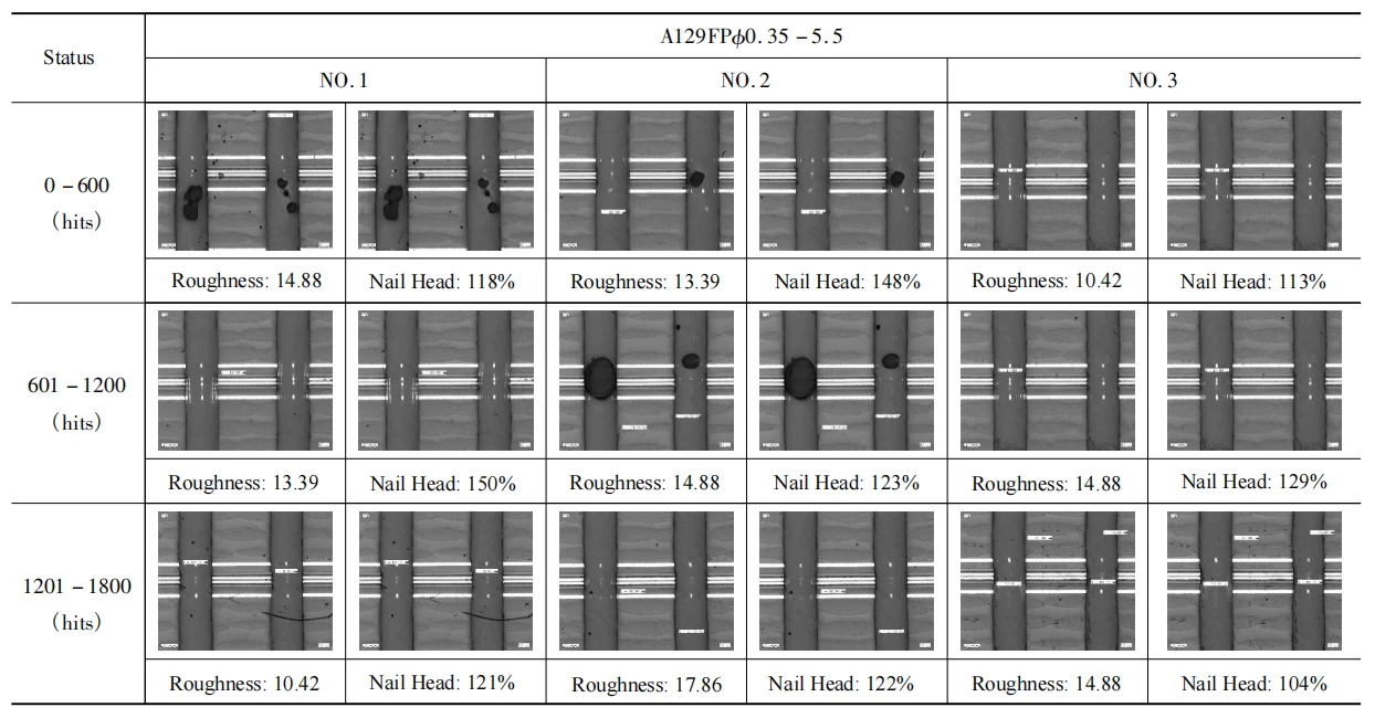
Table 5 A129FP ⌀0.35–5.5 Hole Wall Precision
The optimized results significantly outperformed the pre-optimization tests in the following aspects:
(1) Wear condition: Both drill bits exhibited normal wear patterns.
(2) The holes concentrated within a narrow range, achieving a position accuracy of 3σ + average ≤ 40 μm, which is well below 60 μm. Individual max values reached approximately 80μm, achieving CPK ≥ 2.5.
(3) The hole walls exhibited no internal anomalies when examining the overall cross-section. Both drill bit models produced holes with intact inner coating films and relatively straight wall entrances.
(4) Hole wall roughness < 25μm, pinhead < 150%. The optimized A129FP ⌀0.30 – 5.0 and A129FP ⌀0.35 – 5.5 meet customer requirements.
Inspection and Validation
Micro-drilling quality in flexible PCBs should be verified by cross-section and hole-wall inspection. For each lot or process change, check:
- Copper burr height at entry and exit
- Nailheading severity on inner copper
- Adhesive smear coverage on the hole wall
- Hole-wall roughness in polyimide and adhesive layers
- Delamination at material interfaces
These measurements are more useful than visual inspection alone. They make it possible to isolate whether the issue comes from stack movement, tool wear, or drilling parameters.
[Read more: PCB hole wall quality inspection]
—
Frequently Asked Questions
What is the best drill bit for flexible PCB micro-drilling?
The best drill bit for flexible PCB micro-drilling is typically a sharp, fine-grain carbide micro-drill with geometry designed for mixed thin copper, polyimide, and adhesive stacks. The key is not a single universal type, but a tool that stays sharp enough to cut copper cleanly while resisting abrasive wear from polyimide.
How do you reduce smear when drilling polyimide flex circuits?
Reduce smear by controlling heat at the drill tip. Use sharp drills, moderate cutting speeds, controlled chip loads, and peck drilling to clear chips. Stabilize the stack with entry and backer boards so the drill cuts consistently. If adhesive smear still appears, evaluate tool wear and retract strategy before increasing desmearing aggressiveness.
Why do flex PCB stacks have more burrs than rigid FR-4?
Flex PCB stacks have thin, ductile copper and less rigid support than FR-4. The copper in flexible copper-clad laminate deforms more easily under mechanical pressure, producing burrs and nailheading at the hole entry and exit. Poor stack support, dull drills, and excessive feed make the problem worse.
Can you use the same drilling parameters for flex and rigid PCBs?
Not reliably. Flexible PCB micro-drilling uses different support, tooling, and chip-control requirements because polyimide is abrasive, adhesive layers are soft, and copper is thin. Rigid-board parameters often create excessive heat, smear, burr, and tool wear in flex stacks. Use a flex-specific process and verify by cross-section.
Conclusion
Researchers conducted drilling tests on a highly demanded rigid-flex board material in the electronics industry and optimized the geometric parameters of the FPCB micro-hole drilling.
Results demonstrate that the optimized FPCB micro-hole drilling significantly improves hole wall precision and hole position accuracy, meeting customer requirements and providing a theoretical basis for micro-drill engineering design.





