How Smart Routing Design Extends Flex Circuit Life from Thousands to Millions of Cycles

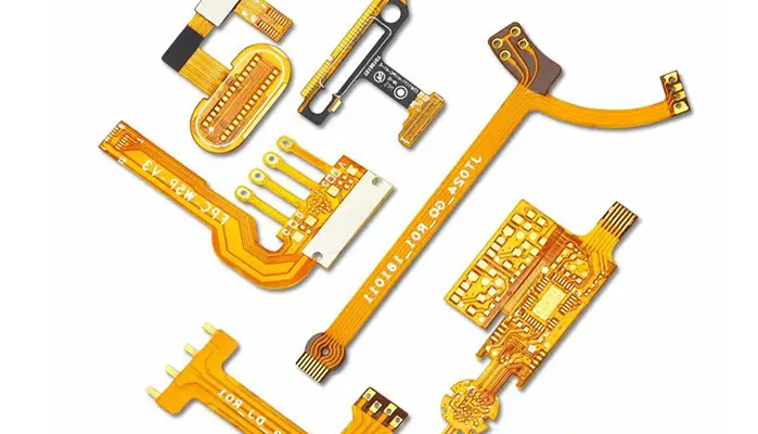
Flexible printed circuits have become essential components in modern electronics, enabling compact designs, reduced assembly complexity, and reliable electrical interconnections in applications where traditional rigid PCBs cannot operate.
From foldable smartphones and wearable devices to medical catheters and industrial robotics, flexible circuits are increasingly expected to survive repeated mechanical movement throughout their service life.
However, dynamic bending remains one of the most challenging aspects of flexible PCB design.
Unlike static flex circuits that are bent once during installation and remain fixed afterward, dynamic flex circuits must endure thousands, hundreds of thousands, or even millions of bending cycles without electrical or mechanical failure.
In these environments, a design that appears electrically perfect can still fail prematurely due to mechanical fatigue.
Many engineers assume that selecting premium materials alone is sufficient to ensure reliability.
While material selection is important, field failures often originate from improper trace routing rather than inadequate materials.
Even the highest-quality rolled annealed copper can crack if traces are routed parallel to the bending axis or if stress concentrations are introduced through poor geometry.
The reality is that trace routing determines how mechanical stress is distributed throughout the flexible circuit.
Proper routing can dramatically increase fatigue life, while poor routing can reduce product lifespan by orders of magnitude.
This guide explores the engineering principles behind dynamic bending, explains why flexible circuits fail, and presents practical routing strategies that help extend flex circuit life from thousands to millions of bending cycles.
What Makes Dynamic Bending Different from Static Flexing?
The first step toward designing a reliable flex circuit is understanding that not all bending applications are the same.
The design requirements for a flexible circuit installed once during assembly are fundamentally different from those for a circuit that moves continuously throughout its operational life.
Dynamic vs. Static Applications
Static flexing, often called “flex-to-install,” occurs when a flexible circuit is bent into position during assembly and remains largely stationary afterward.
Examples include internal interconnects inside consumer electronics, automotive dashboards, and compact industrial equipment.
Dynamic flexing involves continuous or repeated movement during product operation.
In these applications, the flexible circuit functions as both an electrical interconnect and a moving mechanical component.
Table 1 compares the two design environments.
| Characteristic | Static Flexing | Dynamic Flexing |
|---|---|---|
| Number of Bend Cycles | 1–100 | 10,000 to 10,000,000+ |
| Typical Bend Radius | 6–10× Thickness | 20–100× Thickness |
| Copper Type | ED or RA Copper | RA Copper Preferred |
| Design Focus | Packaging Efficiency | Fatigue Resistance |
| Failure Risk | Low | High |
| Typical Applications | Consumer Electronics Assembly | Robotics, Medical Devices, Printers |
Dynamic bending applications are common in modern electronics:
| Application | Dynamic Motion Type |
|---|---|
| Laptop Hinges | Repeated Opening and Closing |
| Medical Catheters | Continuous Flexing and Rotation |
| Printer Heads | High-Frequency Reciprocating Motion |
| Industrial Robotics | Multi-Axis Movement |
| Wearable Electronics | Constant Human Motion |
In these environments, mechanical reliability becomes just as important as electrical performance.
Why Dynamic Bending Causes Copper Fatigue
The primary challenge in dynamic flex circuits is metal fatigue.
Every time a flexible PCB bends, copper conductors experience mechanical deformation.
During bending, the outer surface of the circuit stretches under tensile stress, while the inner surface compresses under compressive stress.
Although these stresses may appear insignificant during a single bending event, repeated loading eventually alters the copper’s microstructure.
Over time, microscopic crystal defects accumulate within the copper foil. This phenomenon is known as work hardening.
As work hardening progresses, the copper becomes less ductile and more brittle. Small cracks begin to form, typically at locations where stress is concentrated.
Once initiated, these cracks gradually propagate through the conductor cross-section during subsequent bending cycles.
Eventually, the remaining conductive area becomes insufficient to carry current, resulting in increased resistance or complete circuit failure.
Research published by IPC and flexible circuit material suppliers consistently shows that fatigue life is strongly influenced by mechanical strain. Even small reductions in conductor strain can increase flex life by several times.
Table 2 illustrates the relationship between mechanical strain and expected fatigue performance.
| Strain Level | Relative Fatigue Life |
|---|---|
| High Strain | Very Low |
| Moderate Strain | Moderate |
| Low Strain | High |
| Very Low Strain | Extremely High |
This relationship explains why seemingly minor routing decisions can have a dramatic effect on long-term reliability.
Golden Rule of Dynamic Routing: Follow the Stress Flow
The most reliable dynamic flex circuits share one common characteristic: their routing geometry follows the natural flow of mechanical stress rather than fighting against it.
Engineers often focus exclusively on electrical connectivity, but successful dynamic flex design requires understanding how mechanical loads travel through the structure.
Understanding Mechanical Stress Paths
When a flex circuit bends, three distinct mechanical regions are created.
The outer surface enters tension and experiences stretching forces. The inner surface enters compression and experiences shortening forces. Between these two regions lies the neutral axis, where theoretical strain approaches zero.
The closer a conductor is positioned to the neutral axis, the less mechanical strain it experiences during bending.
Consequently, one of the primary goals of dynamic flex design is minimizing conductor strain through proper stack-up design and routing geometry.
Why Routing Direction Matters
Routing direction has a profound impact on fatigue life.
When traces are routed perpendicular to the bend axis, the conductor experiences relatively uniform deformation across its width.
Stress is distributed evenly, reducing the likelihood of crack initiation.
In contrast, traces routed parallel to the bend axis repeatedly undergo tensile and compressive loading along their entire length.
This configuration dramatically increases fatigue accumulation and significantly shortens service life.
Table 4 compares these routing approaches.
| Routing Direction | Reliability Performance |
|---|---|
| Perpendicular to Bend Axis | Excellent |
| Angled to Bend Axis | Acceptable |
| Parallel to Bend Axis | Poor |
Because of this behavior, routing traces perpendicular to the bend direction is widely regarded as the single most important routing guideline for dynamic flex circuits.
In practical terms, good routing works with the mechanical motion of the flexible circuit, while poor routing forces copper conductors to absorb stress repeatedly.
The difference can determine whether a product survives thousands of cycles or continues operating reliably for millions.
Designing Around the Neutral Axis
Among all factors that influence dynamic flex reliability, the position of the copper conductor within the stack-up is one of the most important.
Even when identical materials and routing geometries are used, the location of the trace relative to the neutral axis can dramatically affect fatigue life.
Neutral Axis Theory
When a flexible circuit bends, not every layer experiences the same amount of strain.
The outer surface stretches under tensile loading, while the inner surface compresses. Between these two regions lies an imaginary plane known as the neutral axis.
At the neutral axis, the theoretical strain approaches zero.
Materials positioned closer to this plane undergo significantly less deformation during bending than materials located farther away.
The mechanical significance of the neutral axis becomes clear when considering copper fatigue.
Since fatigue damage is directly related to cyclic strain, reducing the strain experienced by conductors can substantially extend service life.
The relationship can be simplified as shown below.
| Distance from Neutral Axis | Relative Strain | Expected Fatigue Life |
|---|---|---|
| Very Close | Very Low | Excellent |
| Moderate Distance | Moderate | Good |
| Far from Neutral Axis | High | Poor |
| Outer Surface | Maximum | Very Poor |
For dynamic flex applications, successful designs seek to position conductors as close as possible to the neutral axis while maintaining manufacturability and electrical performance.
Conductor Placement Strategies
One of the simplest methods for reducing strain is minimizing the distance between the conductor and the neutral axis.
Single-layer flex circuits are often considered the most reliable solution for continuous bending applications because the copper layer can be positioned near the center of the flex structure.
In many dynamic applications, single-layer constructions routinely outperform multilayer alternatives despite having lower routing density.
Table 5 compares common flex constructions.
| Construction | Flexibility | Fatigue Resistance | Routing Density |
|---|---|---|---|
| Single-Layer Flex | Excellent | Excellent | Moderate |
| Double-Sided Flex | Good | Good | High |
| Multilayer Flex | Moderate | Moderate | Very High |
| Rigid-Flex | Application Dependent | Application Dependent | Very High |
For multilayer constructions, designers often employ symmetrical stack-ups.
By balancing dielectric and coverlay thicknesses above and below the conductor layers, the neutral axis can be shifted toward the center of the stack-up, reducing stress concentration.
An asymmetric stack-up may appear acceptable during fabrication, but it can generate uneven strain distribution during operation, accelerating fatigue failures.
Reducing Copper Fatigue
Neutral-axis optimization works best when combined with fatigue-reduction strategies.
One commonly recommended approach is balanced coverlay construction.
When coverlay thicknesses differ significantly between opposite sides of the flex circuit, bending stresses become unevenly distributed.
Balanced coverlays help maintain mechanical symmetry and reduce localized strain concentrations.
Copper thickness also plays a major role in dynamic performance.
Thicker copper increases conductor stiffness, which raises strain during bending. Thinner copper deforms more easily and generally survives significantly more flex cycles.
Table 6 summarizes typical copper selections.
| Copper Weight | Approximate Thickness | Dynamic Flex Suitability |
|---|---|---|
| 1 oz | 35 µm | Limited |
| 1/2 oz | 18 µm | Good |
| 1/3 oz | 12 µm | Excellent |
| Ultra-Thin Copper | <12 µm | Specialized Applications |
For applications requiring hundreds of thousands or millions of cycles, many manufacturers recommend 12–18 μm rolled annealed copper combined with carefully controlled bend radii and balanced stack-ups.
Bend Area Layout Rules
Routing optimization alone cannot ensure reliability if unsuitable structures are placed within active bend regions.
The bend area should be treated as a dedicated mechanical zone where stiffness and stress concentrations are minimized.
Components and Pads
One of the most important design principles is keeping rigid features out of active bending areas.
Surface-mount components, through-hole components, and large solder pads all create localized stiffness.
When the surrounding substrate bends, these rigid structures resist deformation, causing stress to accumulate around their boundaries.
The result is often cracked solder joints, copper fatigue, or coverlay separation.
Table 9 summarizes recommended practices.
| Feature | Dynamic Bend Area Recommendation |
|---|---|
| SMT Components | Avoid |
| Through-Hole Components | Avoid |
| Large Pads | Avoid |
| Test Points | Minimize |
| Passive Components | Place Outside Bend Zone |
As a general guideline, active bend regions should contain only flexible conductors and supporting dielectric materials.
Via Placement Restrictions
Vias introduce abrupt changes in both geometry and stiffness.
The plated barrel structure does not flex as readily as surrounding materials, creating stress concentrations during repeated movement.
Many IPC recommendations advise keeping vias outside dynamic bending zones whenever possible.
A commonly used industry guideline is maintaining a minimum clearance of approximately 2.5 mm (100 mils) between active bend areas and nearby vias, although specific requirements depend on bend radius and application severity.
Table 10 provides typical recommendations.
| Feature | Suggested Clearance from Dynamic Bend |
|---|---|
| Via | ≥ 2.5 mm |
| Component Pad | ≥ 2.5 mm |
| Stiffener Edge | ≥ 2.5 mm |
| Connector Interface | Application Dependent |
Copper Plane Design
Ground planes improve signal integrity and EMI performance, but they also increase stiffness.
Solid copper planes resist deformation and can significantly reduce flexibility.
In dynamic applications, this increased rigidity often leads to higher bending stress.
To balance electrical and mechanical requirements, designers frequently use cross-hatched copper structures.
Table 11 compares both approaches.
| Copper Structure | Flexibility | EMI Shielding | Signal Reference |
|---|---|---|---|
| Solid Plane | Low | Excellent | Excellent |
| Cross-Hatched Plane | High | Good | Good |
| No Plane | Excellent | Limited | Limited |
Cross-hatched patterns preserve much of the flexibility of the base material while maintaining adequate shielding and return-path functionality.
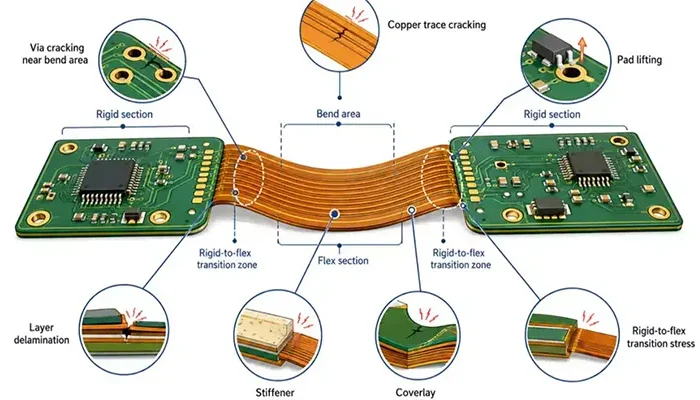
Transition Zone Design
The rigid-to-flex interface is one of the highest-risk regions in any dynamic flex assembly.
Because stiffness changes abruptly at this boundary, bending loads naturally concentrate there.
Successful designs incorporate gradual transitions that distribute stress more evenly across the interface.
Common strategies include:
- Extending coverlay overlap
- Adding strain-relief features
- Avoiding vias near transition boundaries
- Routing traces perpendicular to the interface
Many long-term reliability failures originate at this boundary rather than within the bend area itself.
Dynamic Flex PCB Design Best Practices
Designing for dynamic reliability requires looking beyond individual routing rules and considering the complete mechanical system.
Dynamic Flex Reliability Challenges
Two primary mechanisms dominate dynamic flex failures: work hardening and cyclic fatigue.
Work hardening gradually reduces copper ductility as repeated deformation alters the crystal structure. Cyclic fatigue then propagates cracks through the increasingly brittle conductor.
Both processes accelerate when strain levels exceed design limits.
This is why reducing strain—not merely selecting stronger materials—is the foundation of successful dynamic flex design.
Avoiding the I-Beam Effect
One of the most common multilayer flex design mistakes is trace stacking.
When conductors on opposite layers are placed directly above one another, the structure behaves similarly to an I-beam used in construction.
Although this arrangement increases stiffness, it dramatically reduces flexibility.
Table 12 illustrates the effect.
| Routing Structure | Relative Stiffness | Dynamic Reliability |
|---|---|---|
| Stacked Traces | High | Poor |
| Staggered Traces | Low | Excellent |
Staggering conductors between layers distributes stress more evenly and allows the structure to flex naturally.
Dynamic Routing Recommendations
Experience from aerospace, medical, and industrial applications has led to several consistent recommendations.
Single-layer constructions generally provide the best fatigue performance. Thin rolled annealed copper minimizes strain accumulation. Staggered conductors reduce stiffness. Large bend radii lower cyclic stress. Together, these practices can dramatically extend operational life.
The highest-reliability dynamic flex circuits rarely rely on a single improvement. Instead, they combine multiple strain-reduction techniques throughout the design.
Designing for Millions of Flex Cycles
Products such as robotic systems, medical instruments, and printer mechanisms often require service lives exceeding one million bending cycles.
Achieving this level of durability requires a holistic design approach that integrates material selection, stack-up optimization, routing geometry, and mechanical validation.
Table 13 summarizes common design targets.
| Application Category | Typical Cycle Requirement |
|---|---|
| Consumer Electronics | 10,000–100,000 |
| Industrial Equipment | 100,000–1,000,000 |
| Robotics | 1,000,000+ |
| Medical Devices | 1,000,000+ |
| Aerospace Systems | 1,000,000+ |
Designs intended for these environments typically use rolled annealed copper, large bend radii, balanced stack-ups, staggered conductors, and extensive fatigue testing to validate long-term performance before production release.
Designing for Different Flex Cycle Requirements
One of the most common mistakes in flex PCB development is applying the same routing strategy to every application. In reality, the reliability requirements for a consumer wearable are vastly different from those of a surgical device or aerospace sensor system.
A flexible circuit designed for 10,000 bending cycles may function perfectly in a consumer product, yet fail catastrophically in an industrial robot expected to survive millions of motion cycles. Therefore, routing decisions should always be driven by the target lifecycle requirement.
10,000-Cycle Products: Consumer Electronics
Many consumer products operate within the lower range of flex-cycle requirements. Examples include foldable headphones, laptop display cables, cameras, gaming devices, and household electronics.
Although reliability remains important, these products often prioritize compactness, cost efficiency, and high-density routing.
For applications targeting approximately 10,000 bending cycles, designers can typically use moderate bend radii, double-sided flex constructions, and standard dynamic-routing practices.
Table 14 summarizes common design characteristics.
| Design Parameter | Typical Recommendation |
|---|---|
| Bend Radius | 10–20× Thickness |
| Copper Thickness | 18–35 μm |
| Copper Type | ED or RA Copper |
| Layer Count | 1–2 Layers |
| Ground Planes | Limited Solid Copper |
| Reliability Target | 10,000–50,000 Cycles |
At this level, proper routing geometry and bend management are usually sufficient to achieve product requirements.
100,000-Cycle Products: Industrial Equipment
Industrial automation introduces significantly harsher operating conditions.
Cable carriers, machine vision systems, packaging equipment, and automated assembly machinery often operate continuously for years. In these environments, fatigue resistance becomes a primary design objective.
Engineers frequently adopt larger bend radii, thinner copper conductors, and more aggressive stress-reduction strategies.
Table 15 illustrates common design upgrades.
| Design Parameter | Typical Recommendation |
|---|---|
| Bend Radius | 20–50× Thickness |
| Copper Thickness | 12–18 μm |
| Copper Type | RA Copper |
| Layer Count | Single-Layer Preferred |
| Trace Geometry | Curved Routing Only |
| Reliability Target | 100,000–1,000,000 Cycles |
At this stage, many manufacturers begin performing dedicated fatigue testing before production release.
1,000,000+ Cycle Products: Medical and Aerospace Systems
Medical equipment, aerospace electronics, satellites, avionics systems, and advanced robotics often require service lives exceeding one million bending cycles.
Failure in these applications can have severe operational and safety consequences, making reliability the dominant design consideration.
To achieve ultra-high fatigue performance, designers generally combine:
- Rolled annealed copper
- Thin conductor structures
- Large bend radii
- Single-layer constructions
- Staggered routing
- Extensive qualification testing
Table 16 summarizes typical design targets.
| Design Parameter | High-Reliability Recommendation |
|---|---|
| Bend Radius | 50–100× Thickness |
| Copper Thickness | 12 μm or Less |
| Copper Type | High-Ductility RA Copper |
| Layer Count | Single-Layer Preferred |
| Ground Planes | Cross-Hatched Only |
| Reliability Target | 1,000,000–10,000,000+ Cycles |
These products are typically validated using IPC fatigue testing methods and application-specific qualification protocols.
Routing Adjustments for Each Reliability Level
As lifecycle requirements increase, routing strategies must evolve accordingly.
The relationship between routing complexity and fatigue performance can be summarized below.
| Routing Feature | 10k Cycles | 100k Cycles | 1M+ Cycles |
|---|---|---|---|
| Perpendicular Routing | Recommended | Required | Required |
| Rounded Corners | Recommended | Required | Required |
| Single-Layer Design | Optional | Preferred | Strongly Preferred |
| Staggered Traces | Optional | Recommended | Required |
| Cross-Hatched Planes | Optional | Recommended | Required |
| Dynamic Fatigue Testing | Optional | Recommended | Mandatory |
The key takeaway is that higher reliability requirements demand progressively more aggressive strain-management techniques.
Common Routing Mistakes Engineers Still Make
Despite decades of industry experience and established IPC guidelines, certain routing mistakes continue to appear in flex PCB designs. Most fatigue failures can ultimately be traced back to a small number of recurring design decisions.
Routing Parallel to the Bend
This remains the most common and most damaging routing mistake.
When traces run parallel to the bend axis, the entire conductor length repeatedly experiences tensile and compressive loading. This accelerates work hardening and significantly reduces fatigue life.
Many field failures that appear to be “material problems” are actually routing-orientation problems.
Using Sharp Corners
Sharp corners act as mechanical stress concentrators.
During bending, stress naturally accumulates at abrupt geometric changes. Microcracks frequently originate at these locations before propagating through the conductor.
Large-radius curves distribute stress far more effectively and should always be used in dynamic regions.
Placing Vias in Flex Zones
Vias create rigid structures within a flexible environment.
Repeated motion concentrates strain around the plated barrel and pad interface. Over time, cracking and delamination become likely.
Whenever possible, vias should be relocated outside active bending regions.
Stacking Traces on Opposite Layers
Stacked conductors increase structural stiffness and create the well-known I-beam effect.
Although this arrangement simplifies routing, it significantly reduces flexibility and accelerates fatigue damage.
Staggered conductors remain the preferred solution for multilayer dynamic flex designs.
Overusing Solid Copper Areas
Many designers add large copper pours to improve grounding and shielding.
While electrically beneficial, solid copper dramatically reduces flexibility. In dynamic applications, extensive copper planes often become major contributors to stress concentration.
Cross-hatched structures generally provide a better balance between electrical performance and mechanical durability.
Ignoring Transition Zone Stress
Some engineers focus exclusively on the bend area while overlooking the rigid-to-flex interface.
In reality, many failures originate at transition zones rather than within the bend itself.
Stress-relief features, coverlay overlap, and careful conductor routing are essential for long-term reliability.
Table 17 summarizes the most common failure-causing mistakes.
| Design Mistake | Primary Failure Mechanism |
|---|---|
| Parallel Routing | Copper Fatigue |
| Sharp Corners | Crack Initiation |
| Vias in Bend Areas | Delamination |
| Trace Stacking | I-Beam Effect |
| Solid Copper Planes | Excessive Stiffness |
| Poor Transition Design | Boundary Cracking |
Verification and Testing Before Production
Even the most carefully designed flex circuit should be validated through testing before production release.
Simulation and design guidelines reduce risk, but physical testing remains the only reliable method for verifying long-term fatigue performance.
Dynamic Bend Testing
Dynamic bend testing evaluates a flexible circuit’s ability to withstand repeated motion under controlled conditions.
The most widely recognized methods are derived from IPC-TM-650 testing procedures, which establish standardized approaches for measuring flex endurance.
A typical test fixture repeatedly bends the sample around a specified mandrel radius while monitoring electrical continuity.
Table 18 shows commonly monitored parameters.
| Test Parameter | Typical Value |
|---|---|
| Bend Radius | Application-Specific |
| Test Frequency | 0.5–5 Hz |
| Target Cycles | 10k–10M+ |
| Temperature | Ambient or Elevated |
| Failure Criteria | Open Circuit or Resistance Shift |
Cycle Count Verification
Cycle count alone does not guarantee reliability.
Engineers must ensure that testing conditions accurately replicate real-world operating environments. Differences in bend radius, motion speed, or environmental conditions can significantly affect fatigue performance.
For mission-critical applications, qualification testing often exceeds expected field conditions to provide additional safety margins.
Resistance Monitoring
One of the earliest indicators of fatigue damage is increasing conductor resistance.
Before complete fracture occurs, microscopic cracks reduce the conductor’s effective cross-sectional area. This causes measurable resistance changes.
Many qualification programs define failure thresholds based on resistance variation.
Table 19 summarizes common monitoring criteria.
| Measurement | Typical Acceptance Criterion |
|---|---|
| Resistance Change | Less than 10% |
| Continuity | No Interruption |
| Visual Inspection | No Cracking |
| Delamination | None Observed |
Continuous resistance monitoring allows engineers to identify fatigue onset before catastrophic failure occurs.
Design Simulation
Modern simulation tools provide valuable insight into stress distribution before prototype fabrication.
Finite Element Analysis (FEA) can predict:
- Peak strain locations
- Neutral-axis movement
- Transition-zone stress
- Bend-induced deformation
Although simulation cannot replace physical testing, it significantly reduces development risk and shortens design cycles.
Building Effective Test Coupons
Dedicated fatigue test coupons are often more valuable than testing finished products.
Well-designed coupons isolate the critical routing structures and allow engineers to evaluate fatigue performance economically.
Effective coupons should replicate:
- Actual stack-up
- Trace geometry
- Copper thickness
- Bend radius
- Motion profile
Testing representative coupons early in development can prevent costly redesigns later in the product lifecycle.
Conclusion
Dynamic flex PCB design is fundamentally different from conventional PCB layout. Success depends not only on electrical performance but also on understanding how mechanical stress interacts with conductors throughout the product lifecycle.
Across all applications—from consumer electronics to aerospace systems—the most successful designs consistently focus on three routing decisions.
The Three Most Important Routing Decisions
The first is trace direction. Routing conductors perpendicular to the bend axis remains the single most effective way to reduce fatigue damage.
The second is trace geometry. Smooth curves, gradual transitions, and uniform widths distribute stress far more effectively than sharp corners and abrupt changes.
The third is layer structure. Proper conductor placement, balanced stack-ups, and staggered routing minimize strain and prevent stiffness-related failures.
Designing for Long-Term Reliability
Dynamic flex reliability is not achieved through a single design rule. Instead, it results from a combination of optimized materials, intelligent routing, controlled bend radii, and rigorous validation testing.
When these elements work together, flexible circuits can reliably survive hundreds of thousands—or even millions—of bending cycles.
Final Recommendations for Engineers and Product Designers
Engineers developing dynamic flex circuits should prioritize strain reduction over routing convenience. Mechanical behavior must be considered as early as electrical performance during the design process.
By understanding stress flow, designing around the neutral axis, implementing fatigue-resistant routing strategies, and validating designs through testing, development teams can dramatically improve product reliability while reducing field failures and long-term maintenance costs.
Ultimately, the most durable flex circuits are not simply manufactured correctly—they are routed correctly from the very beginning.
References
- IPC-2223D, Sectional Design Standard for Flexible Printed Boards
- IPC-6013E, Qualification and Performance Specification for Flexible Printed Boards
- IPC-TM-650, Test Methods Manual for Printed Boards
- DuPont™ Pyralux® Flexible Circuit Materials Design Guide
- Rogers Corporation, Flexible Circuit Design Handbook
- Panasonic Electronic Materials, Flexible Circuit Reliability Guide
- All Flex Solutions, Dynamic Flex Circuit Design Recommendations
- Epec Engineering Technologies, Flex PCB Design Guidelines
- NASA Electronic Parts and Packaging Program (NEPP), Flexible Circuit Reliability Studies
- SMTA International Technical Papers on Flex Circuit Fatigue and Reliability

