Rigid PCB vs Flex PCB vs Rigid-Flex PCB: The Complete Engineering Guide

Chapter 1: Why PCB Selection Matters More Than Most Engineers Think
Printed circuit boards (PCBs) are the foundation of modern electronic systems. While components such as processors, sensors, and memory devices often receive the most attention during product development, the PCB architecture itself plays an equally critical role in determining a product’s size, reliability, manufacturability, and long-term performance.
Selecting the wrong PCB technology can increase production costs, complicate assembly processes, reduce reliability, and even lead to premature product failure. As electronic devices continue to become smaller, lighter, and more complex, engineers must carefully evaluate whether a rigid PCB, flexible PCB, or rigid-flex PCB is the most appropriate solution for their application.
The Evolution from Rigid Boards to Flexible Electronics
For decades, rigid printed circuit boards dominated the electronics industry. Traditional consumer products such as desktop computers, televisions, industrial controllers, and telecommunications equipment relied almost exclusively on FR-4-based rigid boards. Their excellent mechanical stability, low manufacturing cost, and mature production ecosystem made them the preferred choice for most electronic designs.
However, the rapid advancement of miniaturized electronics has dramatically changed PCB requirements. Modern devices are expected to deliver greater functionality within increasingly compact form factors. As a result, designers can no longer rely solely on flat, rigid boards connected by bulky wiring harnesses.
The miniaturization trend has accelerated across nearly every industry. Smartphones now integrate multiple cameras, antennas, batteries, and processing units within extremely limited internal space. Smartwatches must fit sophisticated electronics into housings only a few millimeters thick. Electric vehicles require compact sensor modules and battery management systems capable of operating under harsh environmental conditions. Medical devices increasingly demand lightweight and ergonomic designs that conform to the human body.
These challenges have driven the adoption of flexible and rigid-flex PCB technologies. Instead of forcing products to conform to the shape of a circuit board, engineers can now design circuit boards that conform to the shape of the product.
The Four Factors Driving PCB Choice
Although many technical considerations influence PCB selection, four primary factors typically determine whether a rigid, flexible, or rigid-flex design is the most suitable solution.
Space Constraints
Space is often the most influential factor in modern electronic design. Traditional rigid PCBs require flat mounting surfaces and additional interconnection hardware when multiple boards are used. Flexible circuits can fold, bend, and route through three-dimensional spaces, significantly reducing overall product volume.
In some wearable devices, replacing multiple rigid boards and cable assemblies with a single flex circuit can reduce package volume by more than 50%, while simultaneously simplifying assembly.
Reliability Requirements
Reliability becomes increasingly important in mission-critical applications such as aerospace systems, medical equipment, and automotive electronics.
Every connector, cable, and solder joint represents a potential failure point. Flexible and rigid-flex designs can eliminate many of these interconnections by integrating multiple circuit sections into a single assembly. This reduction in mechanical interfaces often improves long-term reliability, particularly in high-vibration environments.
Cost Considerations
Rigid PCBs remain the most economical option for many applications because they utilize widely available materials and mature manufacturing processes.
Flexible and rigid-flex circuits generally require specialized materials such as polyimide, adhesive systems, coverlays, and more complex fabrication processes. Although the initial PCB cost may be higher, the total system cost can sometimes be lower due to reduced assembly labor, fewer connectors, and smaller product enclosures.
Consequently, engineers should evaluate overall product cost rather than focusing solely on PCB fabrication expenses.
Mechanical Movement
Products that experience repeated motion introduce another layer of complexity.
Applications such as foldable displays, printer heads, robotic arms, and medical monitoring devices often require circuits capable of withstanding continuous flexing. In these situations, flexible PCBs provide a clear advantage because they are specifically designed to tolerate dynamic bending without mechanical failure.
Rigid PCBs, by contrast, are best suited for applications where the circuit remains stationary throughout the product’s service life.
Real Product Examples
The impact of PCB selection becomes more apparent when examining actual products.
A modern smartphone typically combines rigid boards and flexible interconnects. The main processor, memory, and power management circuits are mounted on rigid sections, while cameras, displays, and batteries are connected using flexible circuits to maximize internal space utilization.
Smartwatches rely heavily on flexible PCBs because their compact housings leave little room for traditional board-to-board connections. Flex circuits enable designers to wrap electronics around batteries and conform to curved enclosures.
Automotive camera modules frequently employ rigid-flex designs to withstand vibration while minimizing connector usage. The rigid sections support image sensors and processing electronics, while flexible sections allow compact packaging within restricted installation spaces.
Medical sensors, particularly wearable and implantable devices, often utilize flexible circuits because they can conform to human anatomy while maintaining reliable electrical performance during movement.
As electronic products continue to evolve, PCB architecture has become a strategic design decision rather than a simple manufacturing consideration.
Chapter 2: PCB Technologies at a Glance
Understanding the fundamental differences between rigid, flexible, and rigid-flex PCBs is essential before evaluating their suitability for specific applications.
Although all three technologies perform the same basic function of electrically connecting components, their construction methods, mechanical properties, and design capabilities differ significantly.
What Is a Rigid PCB?
A rigid PCB is a circuit board manufactured from solid substrate materials that cannot bend or flex during normal operation. These boards maintain a fixed shape throughout their service life and provide excellent mechanical support for electronic components.
Structure
A typical rigid PCB consists of copper circuitry laminated onto a fiberglass-reinforced epoxy substrate. Multiple copper layers may be stacked together using prepreg insulation layers to create multilayer structures.
The board is protected by solder mask and silkscreen layers, while plated through-holes provide electrical connections between layers.
Materials
FR-4 remains the most widely used rigid PCB substrate material due to its balance of electrical performance, thermal stability, and affordability.
Specialized applications may utilize:
| Material | Typical Application |
|---|---|
| Standard FR-4 | Consumer electronics |
| High-Tg FR-4 | Automotive and industrial systems |
| Rogers Materials | RF and microwave circuits |
| Metal Core PCB | High-power LED systems |
Typical Layer Counts
Rigid PCBs offer the greatest flexibility in layer count.
| PCB Type | Typical Layers |
|---|---|
| Single-Sided | 1 |
| Double-Sided | 2 |
| Multilayer | 4–20+ |
| HDI PCB | 20–40+ |
Advanced networking, server, and aerospace applications commonly utilize multilayer structures exceeding 20 layers.
Advantages
The widespread adoption of rigid PCBs stems from several advantages. They are cost-effective, easy to manufacture, highly stable, and compatible with automated assembly processes. Their ability to support high component densities and complex multilayer routing makes them suitable for a broad range of electronic products.
Limitations
The primary limitation of rigid PCBs is their inability to conform to non-planar geometries. Designers must often incorporate additional cables, connectors, and mounting hardware when integrating rigid boards into compact systems.
What Is a Flex PCB?
Flexible printed circuit boards are constructed using flexible polymer substrates that allow the circuit to bend, twist, or fold without damaging electrical functionality.
Structure
Most flexible circuits use polyimide film as the base material. Copper traces are bonded to the substrate and protected using a coverlay rather than traditional solder mask.
The resulting structure is significantly thinner and lighter than conventional rigid boards.
Materials
Polyimide is the dominant material due to its excellent thermal resistance, flexibility, and mechanical durability.
Common flexible PCB materials include:
| Material | Characteristics |
|---|---|
| Polyimide (PI) | High reliability and thermal stability |
| Polyester (PET) | Lower cost, reduced temperature resistance |
| Adhesive-less PI | Enhanced dynamic flex performance |
Dynamic vs Static Flexing
One of the most important distinctions in flexible circuit design is whether the application requires static or dynamic flexing.
Static flex applications are bent only during installation and remain fixed afterward. Examples include smartphone interconnects and camera modules.
Dynamic flex applications experience continuous movement throughout their operational life. Examples include printer heads, robotic systems, and foldable electronics.
Dynamic applications require larger bend radii, specialized copper structures, and stricter design rules to prevent fatigue failure.
Advantages
Flexible circuits enable significant reductions in weight, volume, and assembly complexity. Their ability to replace connectors and wiring harnesses improves reliability while supporting innovative product designs.
Limitations
Compared with rigid boards, flexible PCBs are more expensive to manufacture and generally support fewer layers. Repair and rework are also more challenging due to the delicate nature of the substrate materials.
What Is a Rigid-Flex PCB?
Rigid-flex PCBs combine rigid and flexible technologies into a single integrated structure.
Structure
A rigid-flex PCB contains one or more flexible layers laminated together with rigid sections. The flexible layers provide electrical continuity between rigid areas while eliminating the need for separate connectors and cables.
The result is a single integrated circuit assembly capable of both structural support and controlled flexibility.
Hybrid Design Concept
Rigid-flex technology effectively merges the strengths of rigid and flexible circuits.
Rigid regions provide stable mounting surfaces for components, connectors, and heat-generating devices. Flexible regions allow folding, bending, and three-dimensional packaging.
This architecture enables highly compact electronic designs that would be difficult or impossible to achieve using traditional rigid boards.
Advantages
Rigid-flex PCBs offer exceptional reliability because they eliminate many mechanical interconnections. They also enable highly compact packaging, improved signal integrity, and reduced assembly complexity.
These benefits make rigid-flex technology particularly attractive for aerospace, defense, medical, and automotive applications.
Limitations
The primary drawbacks are higher manufacturing costs, longer lead times, and increased design complexity. Engineers must carefully consider stackup design, bend regions, and rigid-to-flex transitions to achieve optimal performance.
Chapter 3: Visual Comparison – Which PCB Fits Your Product?
Choosing the appropriate PCB technology requires balancing multiple engineering priorities rather than focusing on a single factor.
The following comparison summarizes the key differences between rigid, flexible, and rigid-flex PCB technologies.
| Attribute | Rigid PCB | Flex PCB | Rigid-Flex PCB |
|---|---|---|---|
| Manufacturing Cost | Lowest | Medium-High | Highest |
| Weight | Highest | Lowest | Medium |
| Space Efficiency | Moderate | Excellent | Excellent |
| Mechanical Flexibility | None | Excellent | Partial |
| Reliability in Vibration | Good | Excellent | Excellent |
| Assembly Complexity | Low | Medium | Low-Medium |
| Design Freedom | Limited | High | Very High |
| Typical Layer Count | 1–20+ | 1–8 | 4–20+ |
| Repairability | Excellent | Difficult | Good |
| Production Lead Time | Short | Medium | Long |
While rigid PCBs remain the preferred choice for cost-sensitive products, flexible and rigid-flex circuits provide substantial advantages when miniaturization, reliability, and packaging efficiency become critical.
Quick Selection Matrix
The table below provides a simplified decision framework for common engineering objectives.
| Product Requirement | Best PCB Type |
|---|---|
| Lowest Cost | Rigid PCB |
| Smallest Device Size | Rigid-Flex PCB |
| Repeated Bending | Flex PCB |
| Highest Reliability | Rigid-Flex PCB |
| Fastest Manufacturing | Rigid PCB |
In practice, no single PCB technology is universally superior. The optimal solution depends on balancing mechanical requirements, electrical performance, manufacturing constraints, reliability expectations, and total system cost. Understanding these trade-offs is the foundation of successful electronic product development.
Chapter 4: The Hidden Costs Engineers Often Overlook
When engineers compare rigid PCBs, flex PCBs, and rigid-flex PCBs, the discussion often centers on fabrication cost. While board price is important, it represents only a fraction of the total product cost. In many projects, the PCB itself accounts for less than 20% of the overall electronic assembly cost, while connectors, cables, labor, testing, field support, and warranty expenses contribute substantially more over the product lifecycle.
As products become smaller and more integrated, system-level economics frequently outweigh PCB fabrication costs. This is particularly true in automotive electronics, aerospace systems, medical devices, and high-end consumer products.
Connector Costs
Traditional rigid-board architectures often require multiple interconnections to connect separate assemblies. These interconnections typically include board-to-board connectors, wire harnesses, ribbon cables, and FFC/FPC connectors.
Each connector introduces additional material costs, assembly steps, inventory management requirements, and potential failure points.
Wire Harnesses
Wire harnesses have long been used to connect rigid PCB assemblies. Although inexpensive individually, they quickly increase overall system cost.
The total cost includes:
- Connector housings
- Crimp terminals
- Wire preparation
- Assembly labor
- Inspection
- Inventory management
For low-volume products, harness costs may exceed the PCB cost itself.
Board-to-Board Connectors
Board-to-board connectors simplify assembly but introduce mechanical limitations and reliability concerns.
High-speed systems often require expensive precision connectors capable of maintaining signal integrity. Connector height can also limit miniaturization opportunities.
FFC/FPC Connectors
Flexible Flat Cable (FFC) and Flexible Printed Circuit (FPC) connectors are commonly used in smartphones, displays, cameras, and wearable electronics.
While compact, they remain additional components that require assembly, testing, and long-term reliability validation.
Many rigid-flex designs eliminate these connectors entirely by integrating flexible interconnections directly into the PCB structure.
Assembly Costs
PCB cost comparisons frequently ignore assembly expenses, which can become significant in high-volume production.
Additional Labor
Each cable, connector, and interconnect requires handling during assembly.
Consider a product containing:
| Assembly Item | Additional Process |
|---|---|
| Wire Harness | Manual installation |
| Connector | Pick-and-place + soldering |
| Cable Assembly | Routing and fastening |
| FFC Connector | Alignment and insertion |
Even a few extra seconds per unit can translate into substantial labor costs when producing hundreds of thousands of products annually.
Additional Testing
Every electrical interconnection must be tested.
More connectors generally mean:
- More continuity testing
- Additional inspection procedures
- Greater risk of assembly errors
Manufacturers often find that reducing connector count simplifies production testing while improving yield.
Increased Failure Points
Reliability engineers frequently cite connectors as one of the most common sources of field failures.
Potential issues include:
| Failure Mechanism | Common Cause |
|---|---|
| Fretting corrosion | Vibration |
| Contact oxidation | Humidity |
| Loose connections | Mechanical shock |
| Pin deformation | Improper assembly |
Reducing interconnects often produces measurable reliability improvements.
Reliability Costs
Reliability-related expenses are rarely visible during initial procurement decisions but can dominate lifetime ownership costs.
Field Failures
A PCB failure discovered during manufacturing is relatively inexpensive to address.
A PCB failure discovered in the field is dramatically more expensive.
Industry studies often estimate that correcting a defect after product deployment can cost tens or hundreds of times more than correcting it during manufacturing.
For critical products such as automotive electronics and medical devices, field failures can trigger product recalls, regulatory investigations, and reputational damage.
Warranty Claims
Warranty expenses can quickly exceed the original savings achieved through lower-cost PCB selection.
Typical warranty costs include:
- Replacement hardware
- Shipping
- Technical support
- Labor reimbursement
- Product downtime
For consumer electronics manufacturers shipping millions of units annually, even a small increase in failure rate can create substantial financial consequences.
Maintenance Costs
Industrial equipment, aerospace systems, and medical devices often operate for years or decades.
Systems containing numerous connectors and cables typically require more maintenance than integrated rigid-flex designs.
Reducing interconnect complexity often lowers long-term maintenance expenses while improving system uptime.
Why a More Expensive PCB Can Reduce Total System Cost
The most expensive PCB is not always the most expensive solution.
Consider the following simplified example:
| Cost Category | Multi-Board Rigid Design | Rigid-Flex Design |
|---|---|---|
| PCB Fabrication | $18 | $42 |
| Connectors | $16 | $0 |
| Cable Assembly | $12 | $0 |
| Assembly Labor | $10 | $4 |
| Testing | $5 | $3 |
| Total Cost | $61 | $49 |
Although the rigid-flex board costs more than twice as much to fabricate, the overall system cost is lower.
This is why industries such as aerospace, medical electronics, and advanced consumer devices increasingly adopt rigid-flex architectures despite higher board fabrication costs.
Chapter 5: Engineering Design Rules for Flex PCBs
Flexible PCBs offer unique advantages, but they also introduce mechanical considerations that do not exist in rigid board designs. Successful flex PCB implementation requires understanding how bending affects copper conductors, dielectric materials, vias, and solder joints.
Poor flex design often results in cracked traces, delamination, and premature fatigue failures.
Static Bend vs Dynamic Bend
One of the first design decisions involves determining whether the circuit will experience static or dynamic bending.
Static bending occurs only during installation.
Examples include:
- Smartphone display connections
- Camera modules
- Laptop hinge interconnects
Dynamic bending involves repeated movement throughout product life.
Examples include:
- Printer heads
- Robotics
- Foldable displays
- Medical monitoring equipment
Dynamic applications require significantly stricter design rules.
| Bend Type | Typical Movement |
|---|---|
| Static | One-time or infrequent |
| Semi-Dynamic | Limited cycles |
| Dynamic | Continuous cycles |
Bend Radius Calculation
The minimum bend radius is among the most important flex PCB design parameters.
According to IPC-2223 guidelines, bend radius depends on flex thickness and application type.
The general relationship is:
r = k \times h
Where:
- r = minimum bend radius
- h = flex thickness
- k = bend ratio factor
Typical recommendations are shown below.
| Flex Type | Stable Bend | Dynamic Bend |
|---|---|---|
| Single Layer | 10× thickness | 100× thickness |
| Double Layer | 10× thickness | 150× thickness |
| Multilayer | 20× thickness | Not recommended |
For example, a 0.10 mm thick single-layer flex circuit intended for dynamic operation should maintain a bend radius of approximately 10 mm.
Trace Routing Rules
Copper routing strongly influences flex circuit reliability.
Repeated bending generates mechanical stress within conductors. Proper routing minimizes stress concentration and extends flex life.
Avoid 90° Corners
Sharp corners act as stress concentrators.
During repeated flexing, cracks frequently initiate at abrupt directional changes.
Use Curved Traces
Smooth curved routing distributes mechanical strain more evenly.
Rounded trace geometries improve fatigue resistance and reduce localized stress accumulation.
The difference may appear minor on CAD software but can dramatically improve durability during long-term flexing.
Teardrops and Anchors
Teardrops strengthen trace-to-pad transitions.
Anchors improve copper adhesion to flexible substrates.
These features are particularly valuable near:
- Pads
- Vias
- Connector interfaces
- High-stress regions
Ground Plane Design
Solid copper planes that work well in rigid boards often perform poorly in flex circuits.
Large continuous copper areas:
- Reduce flexibility
- Increase stiffness
- Promote crack formation
Many designers use hatched or cross-hatched ground planes to balance electrical performance and mechanical flexibility.
| Ground Style | Flexibility |
|---|---|
| Solid Plane | Low |
| Cross-Hatched Plane | High |
Via Placement Guidelines
Vias represent natural stress concentration points.
Best practice dictates keeping vias outside bend regions whenever possible.
| Feature | Recommended Distance |
|---|---|
| Via to Bend Area | ≥1 mm |
| PTH to Flex Zone | ≥1 mm |
| NPTH to Flex Zone | ≥1 mm |
Placing vias directly inside flex zones significantly increases fatigue risk.
Component Placement Rules
Components should generally remain outside active bending areas.
Heavy components create localized stress concentrations that accelerate solder joint fatigue.
Typical placement recommendations include:
| Component Type | Placement Recommendation |
|---|---|
| BGA | Rigid or stiffened area |
| Connectors | Stiffened area |
| IC Packages | Non-flex zone |
| Passive Components | Minimize in bend area |
FR-4 or polyimide stiffeners are commonly added beneath component regions to provide mechanical support.
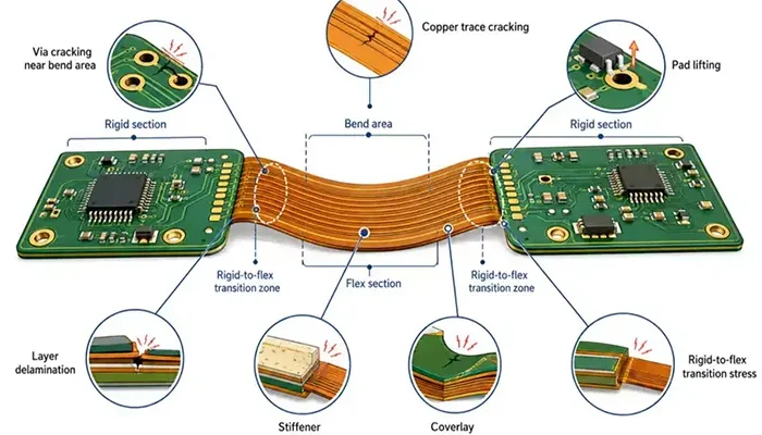
Common Flex PCB Failure Modes
Most flex PCB failures originate from mechanical stress.
The most common failure mechanisms include:
| Failure Mode | Typical Cause |
|---|---|
| Copper Cracking | Excessive bending |
| Coverlay Delamination | Poor adhesion |
| Via Failure | Flexing near vias |
| Solder Joint Fatigue | Component movement |
| Conductor Fracture | Dynamic flex cycles |
Proper adherence to IPC-2223 design practices can significantly reduce these risks.
Chapter 6: Engineering Design Rules for Rigid-Flex PCBs
Rigid-flex PCBs combine rigid and flexible technologies within a single structure. While this approach offers exceptional packaging efficiency and reliability, it introduces unique design challenges that require careful engineering.
Understanding the Rigid-to-Flex Transition
The transition between rigid and flexible regions represents the most critical area of a rigid-flex PCB.
Mechanical strain naturally concentrates at this interface during bending.
Poorly designed transitions often become the first failure location.
Engineers commonly improve durability by:
- Using gradual transitions
- Increasing copper support
- Avoiding abrupt geometry changes
- Reinforcing critical areas
Stackup Planning
Successful rigid-flex designs begin with stackup development.
Typical considerations include:
| Parameter | Design Objective |
|---|---|
| Flex Layer Count | Minimize stiffness |
| Copper Weight | Balance reliability and flexibility |
| Adhesive Selection | Improve durability |
| Coverlay Thickness | Protect conductors |
A symmetrical stackup generally improves dimensional stability and manufacturing yield.
Stiffener Design
Stiffeners are frequently incorporated into rigid-flex assemblies.
Common materials include:
| Material | Primary Purpose |
|---|---|
| FR-4 | Component support |
| Polyimide | ZIF reinforcement |
| Stainless Steel | Maximum rigidity |
| Aluminum | Heat dissipation |
Stiffeners allow components to be mounted securely while preserving flexibility elsewhere.
Stress Concentration Prevention
Mechanical stress can be minimized through thoughtful layout techniques.
Designers often employ:
- Filleted corners
- Rounded cutouts
- Teardrop pads
- Tapered transitions
These features reduce localized strain and improve long-term reliability.
High-Speed Signal Routing
Rigid-flex boards increasingly support high-speed digital systems.
Examples include:
- PCIe
- USB 3.x
- HDMI
- MIPI
- Automotive Ethernet
Maintaining controlled impedance across rigid-flex transitions requires careful stackup and routing management.
| Signal Type | Typical Impedance |
|---|---|
| Single-Ended | 50 Ω |
| Differential Pair | 90–100 Ω |
Proper impedance control becomes particularly important above several gigahertz.
Thermal Design Considerations
Flexible materials generally dissipate heat less effectively than FR-4.
Designers should place:
- Processors
- Power converters
- RF amplifiers
- High-current devices
within rigid sections whenever possible.
Thermal vias, copper pours, and metal reinforcement can further improve thermal performance.
Reliability Enhancement Techniques
High-reliability industries frequently implement additional safeguards.
These may include:
| Technique | Benefit |
|---|---|
| Adhesive-less Construction | Improved flex life |
| Rolled Annealed Copper | Better fatigue resistance |
| Reinforced Bend Zones | Reduced stress |
| Controlled Bend Radius | Extended service life |
Such practices are especially common in aerospace, defense, and medical electronics.
Chapter 7: Flex PCB with Stiffeners vs Rigid-Flex PCB
Among all PCB technologies, few topics generate more confusion than the distinction between flex circuits with stiffeners and rigid-flex PCBs.
At first glance, both appear to contain rigid and flexible regions. However, their construction, functionality, and intended applications differ substantially.
Why Engineers Confuse These Two Technologies
Both technologies may contain:
- Flexible substrates
- FR-4 reinforcement
- Component mounting areas
- ZIF connectors
Visually, they often look similar.
The key difference lies in whether the rigid portions participate in the electrical interconnection structure.
Structural Differences
A flex PCB with stiffeners remains fundamentally a flexible circuit.
The stiffener serves only a mechanical purpose.
A rigid-flex PCB integrates rigid and flexible layers into a unified laminated structure.
| Feature | Flex + Stiffener | Rigid-Flex |
|---|---|---|
| Electrical Interconnect | Flex only | Rigid and flex |
| Plated Through Holes | Limited | Full support |
| Structural Integration | Mechanical only | Electrical + mechanical |
Functional Differences
Flex circuits with stiffeners primarily provide:
- Connector support
- Component support
- Thickness control
- Wear resistance
Rigid-flex boards additionally provide:
- Integrated board-to-board interconnection
- Connector elimination
- Higher packaging density
- Greater design flexibility
Cost Comparison
From a fabrication perspective, flex circuits with stiffeners are generally less expensive.
| Technology | Relative Cost |
|---|---|
| Flex + Stiffener | 1× |
| Rigid-Flex | 2×–4× |
However, fabrication cost alone rarely tells the full story.
Reliability Comparison
Rigid-flex assemblies often achieve higher system-level reliability because they eliminate connectors and cables.
| Reliability Factor | Flex + Stiffener | Rigid-Flex |
|---|---|---|
| Connector Count | Higher | Lower |
| Vibration Resistance | Good | Excellent |
| Mechanical Integration | Moderate | Excellent |
For mission-critical applications, these advantages can outweigh the higher fabrication cost.
Assembly Comparison
Assembly complexity often favors rigid-flex solutions.
Flex circuits with multiple stiffeners may require:
- Additional fixtures
- Connector installation
- Cable routing
- Manual handling
Rigid-flex boards simplify many of these processes by integrating the entire assembly into a single structure.
Which One Should You Choose?
The answer depends on application requirements.
Consumer Electronics
Smartphones, tablets, cameras, and wearables often benefit from rigid-flex designs because of extreme space constraints and high-volume manufacturing requirements.
Medical Devices
Medical equipment prioritizes reliability, miniaturization, and reduced interconnect count.
Rigid-flex technology is frequently the preferred solution.
Industrial Products
Industrial systems often prioritize cost and maintainability.
Flex circuits with stiffeners may provide sufficient performance while reducing procurement costs.
Aerospace Applications
Aerospace electronics place enormous emphasis on reliability, vibration resistance, and weight reduction.
Rigid-flex PCBs are widely adopted because they eliminate connectors, reduce mass, and improve long-term durability under extreme operating conditions.
Continuing your article, here is a professional draft for Chapters 8–11 and the Conclusion section.
Chapter 8: Industry-Specific PCB Selection Guide
Selecting the optimal PCB technology requires more than understanding the differences between rigid, flex, and rigid-flex constructions. Engineers must also consider the unique mechanical, electrical, environmental, and regulatory requirements of their target industry.
A PCB solution that works perfectly in a consumer device may fail to meet the reliability expectations of an aerospace system or the durability requirements of an automotive application. Understanding industry-specific design priorities helps engineers make informed decisions that balance performance, reliability, manufacturability, and cost.
Consumer Electronics
Consumer electronics represent one of the largest PCB markets globally. Product developers continuously pursue thinner profiles, lighter weight, increased functionality, and lower manufacturing costs.
Smartphones
Modern smartphones are among the most densely packed electronic products ever manufactured. A typical flagship smartphone contains multiple cameras, batteries, antennas, sensors, wireless charging systems, and high-speed processors.
Rigid-flex PCBs have become increasingly common because they allow engineers to fold circuits around batteries and structural components while minimizing connector usage. Flexible circuits are frequently used for display interconnects, camera modules, and side-button assemblies.
| Requirement | Preferred PCB |
|---|---|
| Main logic board | HDI Rigid PCB |
| Display connection | Flex PCB |
| Camera module interconnect | Flex PCB |
| Space-constrained modules | Rigid-Flex PCB |
Tablets
Tablets generally have more internal space than smartphones, allowing a greater use of rigid boards. However, flexible circuits remain essential for display interfaces, touch panels, cameras, and battery connections.
Many premium tablets utilize rigid-flex designs to reduce assembly complexity while improving reliability.
Smart Home Products
Smart speakers, security cameras, thermostats, and IoT devices prioritize cost efficiency and manufacturability.
Most smart home products continue to rely heavily on rigid PCBs because the available enclosure volume reduces the need for flexible interconnections.
However, compact devices such as smart doorbells and wireless sensors increasingly adopt flex circuits to improve packaging efficiency.
Automotive Electronics
Automotive electronics present a unique challenge because they must operate reliably under vibration, temperature extremes, humidity, and long service lifetimes.
Vehicle electronics are often designed to meet operational temperature ranges from -40°C to +125°C, with some under-hood systems experiencing even harsher conditions.
ADAS Systems
Advanced Driver Assistance Systems (ADAS) incorporate radar sensors, cameras, LiDAR modules, and powerful processors.
These systems require:
- High reliability
- Excellent signal integrity
- Resistance to vibration
- Compact packaging
Rigid-flex PCBs are frequently selected because they reduce connector count while improving mechanical robustness.
Camera Modules
Automotive camera systems operate in tight spaces and often experience significant vibration.
Rigid-flex designs provide stable mounting regions for image sensors while allowing flexible routing through constrained installation areas.
EV Battery Systems
Electric vehicles contain numerous battery management and monitoring circuits.
Rigid PCBs remain common within battery management systems because they offer excellent thermal performance and cost efficiency.
Flexible circuits are often incorporated for cell monitoring and sensing applications where routing space is limited.
| Automotive Application | Typical PCB Selection |
|---|---|
| BMS Controller | Rigid PCB |
| Battery Monitoring Harness | Flex PCB |
| Camera Module | Rigid-Flex PCB |
| Radar Sensor | Rigid-Flex PCB |
| Infotainment System | Rigid PCB |
Medical Devices
Medical electronics demand exceptional reliability, miniaturization, and compliance with strict regulatory requirements.
Device failure may directly impact patient safety, making reliability one of the primary design drivers.
Wearables
Health-monitoring devices such as smart patches, ECG monitors, glucose sensors, and fitness trackers benefit greatly from flexible circuits.
The ability to conform to body contours improves comfort while enabling compact form factors.
Diagnostic Equipment
Portable ultrasound systems, imaging devices, and laboratory analyzers frequently employ rigid-flex architectures.
These systems benefit from reduced wiring complexity and improved reliability.
Implantable Devices
Pacemakers, neurostimulators, and implantable monitoring devices represent some of the most demanding PCB applications.
Flexible and rigid-flex circuits are often selected because they:
- Minimize size
- Reduce weight
- Improve reliability
- Conform to anatomical structures
| Medical Application | Typical PCB Type |
|---|---|
| Wearable Sensor | Flex PCB |
| Portable Diagnostic Device | Rigid-Flex PCB |
| Implantable Device | Flex or Rigid-Flex |
| Medical Controller | Rigid PCB |
Aerospace and Defense
Aerospace and defense systems operate in environments where reliability is often more important than cost.
Reducing weight while maintaining electrical and mechanical integrity remains a primary design objective.
Satellites
Every gram launched into orbit carries significant cost implications.
Flexible and rigid-flex circuits enable engineers to reduce mass while maximizing packaging density.
Avionics
Aircraft avionics systems experience continuous vibration, thermal cycling, and demanding reliability requirements.
Rigid-flex PCBs have become common because they eliminate connectors that could fail during long-term operation.
Mission-Critical Electronics
Defense electronics, guidance systems, and communications equipment require exceptional durability.
Rigid-flex architectures are frequently chosen due to their superior resistance to vibration and shock.
| Aerospace Application | Preferred PCB |
|---|---|
| Satellite Electronics | Rigid-Flex PCB |
| Flight Control Systems | Rigid-Flex PCB |
| Radar Systems | Rigid PCB |
| Guidance Electronics | Rigid-Flex PCB |
Industrial Automation
Industrial environments expose electronics to vibration, dust, humidity, chemicals, and continuous operation.
Design priorities typically include reliability, serviceability, and long-term maintainability.
Robotics
Modern robotic systems contain numerous moving joints and articulated assemblies.
Flexible circuits are often used to replace traditional cable harnesses, reducing weight and improving reliability.
Motion Control Systems
Servo drives, motor controllers, and industrial automation equipment generally use rigid PCBs because they require robust thermal management and support for higher power levels.
Sensors
Industrial sensors frequently employ flex circuits when installation space is limited or unusual geometries must be accommodated.
| Industrial Application | Recommended PCB |
|---|---|
| Robotics | Flex PCB |
| Motion Controllers | Rigid PCB |
| Industrial Sensors | Flex PCB |
| PLC Systems | Rigid PCB |
Chapter 9: 10 Costly PCB Design Mistakes to Avoid
Even experienced engineers occasionally encounter PCB design issues that lead to manufacturing delays, reliability failures, or increased costs. Understanding these common mistakes can significantly improve project outcomes.
Ignoring Bend Radius Requirements
One of the most common flex PCB failures occurs when designers specify bend radii that are too small for the selected stackup.
Excessive strain can cause copper cracking, substrate damage, and premature fatigue failures.
Placing Vias in Bend Areas
Vias create localized stress concentration points.
When placed directly inside flex zones, they become susceptible to fatigue cracking and electrical failure.
Using the Wrong Copper Type
Rolled Annealed (RA) copper provides superior fatigue resistance compared to Electro-Deposited (ED) copper.
Selecting the wrong copper type for dynamic applications can dramatically shorten product life.
Incorrect Stackup Planning
Poor stackup design may result in:
- Uneven stress distribution
- Reduced flexibility
- Signal integrity issues
- Manufacturing challenges
Symmetrical constructions generally provide better mechanical stability.
Poor Transition Design
Rigid-to-flex transitions represent critical stress points.
Abrupt geometry changes often lead to delamination and conductor fractures.
Overusing Connectors
Connectors increase:
- Cost
- Assembly complexity
- Failure risk
Many rigid-flex designs can eliminate connectors entirely.
Ignoring Assembly Constraints
A PCB that is electrically functional but difficult to assemble can create significant production challenges.
Designers should consider manufacturing processes early in development.
Underestimating Thermal Issues
Flexible substrates generally provide lower thermal conductivity than FR-4.
Improper thermal planning can shorten component life and reduce reliability.
Over-Specifying Layer Counts
Additional layers increase fabrication complexity and cost.
Many designs can achieve the required functionality with fewer layers through improved routing strategies.
Selecting the Wrong PCB Technology
Perhaps the most expensive mistake is choosing a PCB architecture that does not align with product requirements.
The cheapest PCB is not always the most economical solution at the system level.
Chapter 10: PCB Selection Flowchart
Engineers often ask a simple question:
“Which PCB technology should I choose?”
The answer becomes much clearer when evaluated through a structured decision process.
Step 1: Does the Product Need Bending?
The first question determines whether flexibility is required.
If no bending is necessary, a rigid PCB is usually the most economical and practical solution.
If bending is required, continue to the next step.
Step 2: Is the Flex Dynamic or Static?
Dynamic bending involves repeated motion throughout the product lifecycle.
Examples include:
- Robotics
- Foldable devices
- Printer systems
Static bending typically occurs only during installation.
Applications requiring continuous motion generally favor flex PCBs.
Step 3: Are Connectors Acceptable?
If connectors are acceptable and space is available, a combination of rigid PCBs and flex circuits may be sufficient.
If connector elimination is a priority, rigid-flex designs become attractive.
Step 4: What Is the Reliability Requirement?
Mission-critical applications often justify the additional investment associated with rigid-flex technology.
Consumer products with lower reliability demands may prioritize cost efficiency.
Step 5: What Is the Cost Target?
Budget constraints remain important.
Engineers should evaluate:
- PCB fabrication cost
- Assembly cost
- Connector cost
- Reliability cost
- Maintenance cost
rather than considering PCB price alone.
Final Decision Tree
| Design Requirement | Recommended PCB |
|---|---|
| Lowest Cost | Rigid PCB |
| Dynamic Bending | Flex PCB |
| Connector Elimination | Rigid-Flex PCB |
| Maximum Reliability | Rigid-Flex PCB |
| High-Power Electronics | Rigid PCB |
| Ultra-Compact Packaging | Rigid-Flex PCB |
| Wearable Devices | Flex PCB |
Chapter 11: Future Trends in PCB Technology
PCB technology continues to evolve in tandem with advancements in electronics, materials science, and manufacturing processes.
Several emerging trends are shaping the next generation of electronic products.
Foldable Consumer Electronics
Foldable smartphones, tablets, and laptops are driving demand for ultra-reliable dynamic flex circuits.
Future designs will require materials that can withstand hundreds of thousands of bending cycles.
Ultra-Thin Medical Devices
Healthcare is increasingly moving toward wearable and implantable electronics.
Flexible circuits enable devices that conform naturally to the human body while reducing patient discomfort.
EV Electronics
Electric vehicles contain significantly more electronics than conventional automobiles.
Advanced battery systems, sensors, and autonomous driving platforms will continue increasing demand for rigid-flex technologies.
High-Density Rigid-Flex Designs
As packaging density increases, rigid-flex architectures will support:
- Higher layer counts
- HDI structures
- Microvias
- Embedded components
These capabilities enable compact systems with greater functionality.
Flexible Hybrid Electronics
Flexible Hybrid Electronics (FHE) combine printed electronics, sensors, flexible substrates, and semiconductor devices into highly integrated systems.
FHE technology is expected to expand rapidly in healthcare, IoT, and wearable markets.
AI and IoT Hardware Integration
Artificial intelligence and IoT devices require increasing numbers of sensors, wireless interfaces, and edge-processing components.
Future PCB architectures must support:
- Higher component density
- Reduced power consumption
- Compact packaging
- Enhanced reliability
Flexible and rigid-flex technologies will play an increasingly important role in these applications.
Conclusion
PCB selection is far more than a fabrication decision—it is a strategic engineering choice that directly influences product performance, reliability, manufacturability, and total lifecycle cost.
Throughout this guide, we have examined the strengths and limitations of rigid PCBs, flex PCBs, and rigid-flex PCBs across multiple industries and application environments.
Key Takeaways
No single PCB technology is universally superior.
The optimal solution depends on the specific requirements of the application, including mechanical constraints, reliability expectations, production volume, environmental conditions, and budget considerations.
When to Choose a Rigid PCB
Rigid PCBs remain the preferred option when:
- Cost is the primary concern.
- The product does not require bending.
- High layer counts are needed.
- Thermal management is critical.
- Manufacturing simplicity is desired.
Typical applications include industrial controllers, power electronics, networking equipment, and consumer appliances.
When to Choose a Flex PCB
Flex circuits are most suitable when:
- Dynamic or static bending is required.
- Weight reduction is important.
- Space is extremely limited.
- Cable replacement is desirable.
Common applications include wearables, medical sensors, cameras, robotics, and foldable electronics.
When to Choose a Rigid-Flex PCB
Rigid-flex technology becomes the optimal choice when:
- Reliability is paramount.
- Connector elimination is beneficial.
- Three-dimensional packaging is required.
- Product miniaturization is critical.
- Long-term maintenance costs must be minimized.
These advantages explain their widespread adoption in aerospace, defense, medical, automotive, and premium consumer electronics.
Final Engineering Recommendations
Before selecting any PCB technology, engineers should evaluate the entire system rather than focusing solely on PCB fabrication costs.
A thorough analysis should include:
- Mechanical requirements
- Electrical performance
- Assembly complexity
- Reliability targets
- Serviceability
- Lifecycle costs
In many cases, a more expensive PCB can deliver a lower total system cost while improving reliability and simplifying manufacturing. The most successful PCB designs emerge when electrical, mechanical, manufacturing, and reliability considerations are balanced from the earliest stages of product development.
By understanding the tradeoffs between rigid, flex, and rigid-flex technologies, engineers can make informed decisions that lead to more reliable products, better user experiences, and stronger long-term business outcomes.
Recommended references for the full article:
- IPC-2221: Generic Standard on Printed Board Design
- IPC-2223: Sectional Design Standard for Flexible Printed Boards
- IPC-6013: Qualification and Performance Specification for Flexible Printed Boards
- IPC-6012: Qualification and Performance Specification for Rigid Printed Boards
- IPC-6018: Qualification and Performance Specification for High Frequency PCBs
- NASA Electronic Parts and Packaging Program (NEPP)
- MIL-HDBK-217 Reliability Prediction Handbook
- IEC 61189 PCB Test Methods
- HDI Handbook (IPC)
- Major PCB manufacturers’ flex and rigid-flex design guidelines (JLCPCB, Sierra Circuits, AdvancedPCB, TTM Technologies, NCAB Group, Würth Elektronik)

