IPC-6013 flex PCB qualification – Things to Know

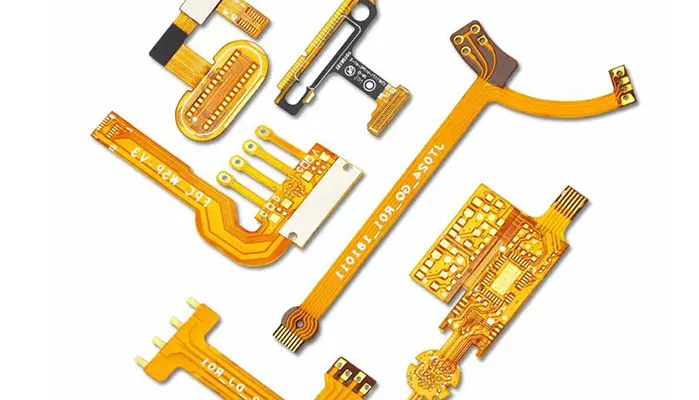
Flexible printed circuit boards (FPCs) are widely used in compact electronics, wearables, automotive systems, and medical devices. Yet despite mature manufacturing processes and standardized testing, flex PCB failures still occur in real-world applications.
This gap between “passing inspection” and “surviving field conditions” is exactly where IPC-6013 becomes critical.
1. Why Flex PCB Failures Still Happen (Even After Testing)
A flex PCB can pass all standard electrical and visual inspections and still fail once deployed in a bending or vibration environment. This contradiction is not rare—it is structural.
In practice, the most expensive failures are not manufacturing defects caught during inspection, but in-service fatigue failures, including:
- Intermittent open circuits after repeated bending
- Copper trace cracking under dynamic motion
- Delamination between copper and substrate layers
- Performance drift caused by microstructural damage
Industry reliability studies (IPC and iNEMI reports) consistently show that mechanical fatigue accounts for a significant portion of field returns in flex assemblies, especially in dynamic flex applications such as foldable devices and automotive modules.
The core misunderstanding is this:
IPC-6013 is not a pass/fail checklist—it is a risk management framework.
2. What Makes Flex PCBs Fundamentally Different
2.1 Flex is not just a thinner PCB
Unlike rigid PCBs, flex circuits are designed for continuous mechanical deformation. That means stress is not static—it is cyclical, directional, and cumulative.
| Characteristic | Rigid PCB | Flex PCB |
|---|---|---|
| Mechanical stress | Minimal | Continuous |
| Failure mode | Shock/thermal | Fatigue-driven |
| Design priority | Electrical integrity | Mechanical + electrical coexistence |
| Lifetime limitation | Thermal aging | Bend cycles + environment |
In other words, flex PCBs are mechanical systems carrying electrical function, not just electronic substrates.
2.2 Hidden failure modes rigid PCB standards do not fully cover
Traditional PCB qualification focuses heavily on electrical continuity and thermal endurance. Flex introduces additional degradation mechanisms:
Copper fatigue under bending
Repeated strain causes grain boundary slip and microcrack propagation, especially in rolled-annealed copper.
Adhesive creep and interlayer separation
Polyimide-copper adhesion weakens under cyclic stress and elevated temperature.
Thermo-mechanical coupling damage
Expansion mismatch between copper (≈17 ppm/°C) and polyimide (≈20–30 ppm/°C depending on formulation) induces cyclic shear stress.
These mechanisms are cumulative and often invisible until field failure occurs.
2.3 Why IPC-6013 exists
IPC-6013 was developed specifically to address the gap between:
- Electrical functionality (IPC-6012 concepts)
- Mechanical survivability under flexing conditions
It defines performance, structural, and environmental expectations for flexible circuits across different application risks.
3. IPC-6013 in One Sentence: A Manufacturing Risk Filter, Not Just a Standard
If reduced to a single engineering concept, IPC-6013 is:
A structured system to align product design, material selection, and manufacturing tolerances with expected mechanical reliability risk.
It does not simply say “this is acceptable or not.” Instead, it governs:
- Material qualification (polyimide type, copper type, adhesive systems)
- Process variability limits (etching, lamination, plating consistency)
- Reliability expectations based on application class
A common engineering mistake is treating IPC-6013 like a compliance certificate rather than a probabilistic reliability model.
4. The Three Layers of IPC-6013 Qualification You Must Understand
4.1 Layer 1: Performance Class (Risk Definition)
IPC-6013 defines three performance classes:
| Class | Application | Failure tolerance | Typical use cases |
|---|---|---|---|
| Class 1 | Consumer electronics | Acceptable failure over time | Toys, low-cost devices |
| Class 2 | Industrial electronics | Moderate reliability required | Automotive infotainment, industrial controllers |
| Class 3 | High-reliability systems | Near-zero failure tolerance | Medical implants, aerospace, defense |
A critical insight from reliability engineering is that moving from Class 2 to Class 3 can increase manufacturing cost by 30–80%, largely due to stricter inspection, materials, and process control.
But the real tradeoff is not cost—it is risk exposure reduction over product lifetime.
4.2 Layer 2: Structural Type (What you are building)
IPC-6013 classifies flex structures into multiple configurations:
- Single-layer flex
- Double-layer flex with plated through holes (PTH)
- Multilayer flex circuits
- Rigid-flex hybrid assemblies
Each increase in structural complexity introduces additional interfaces—each interface is a potential failure boundary.
Empirical reliability data from flex testing labs shows:
| Structure type | Relative fatigue risk |
|---|---|
| Single-layer flex | Low |
| Double-layer flex | Medium |
| Multilayer flex | High |
| Rigid-flex hybrid | Very high (if poorly designed) |
The dominant issue is not electrical complexity but mechanical discontinuity between layers and materials.
4.3 Layer 3: Use Conditions (Most ignored but most critical)
This layer determines real-world survival more than any fabrication parameter.
Flex PCBs behave very differently depending on how they are used:
- Static flex: One-time or low-cycle bending during installation
- Dynamic flex: Continuous repetitive motion (hinges, moving arms)
- Harsh environment flex: Combined heat, vibration, humidity exposure
A key industry observation is that:
Most field failures occur not because the PCB was poorly manufactured, but because the actual use condition exceeded the assumed qualification model.
Engineering Insight: Why IPC-6013 Misunderstandings Cause Failures
Many engineering teams assume:
“If it passes IPC-6013 testing, it is safe in all applications.”
This is incorrect.
IPC-6013 assumes that the correct class, structure, and use case were selected at design time. If any of these assumptions are wrong, the qualification becomes invalid.
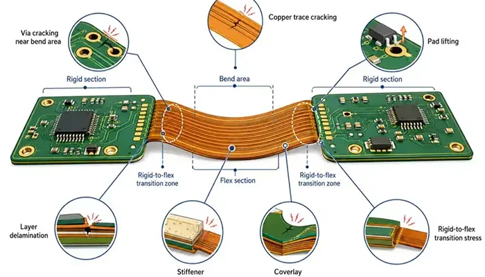
5. Where IPC-6013 Really Gets Strict (Critical Manufacturing Zones)
While IPC-6013 defines system-level qualification, its strictness is most visible in a few high-risk manufacturing zones. These are not abstract compliance points—they are the actual locations where field failures originate.
5.1 Copper integrity in bending zones
Copper is the primary electrical conductor, but in flex PCBs it is also a mechanical fatigue material. Under repeated deformation, copper behaves less like a conductor and more like a ductile metal under cyclic strain.
A widely observed reliability issue in flex circuits is fatigue-driven microcrack propagation, especially at outer bend radii where tensile strain is highest.
Key failure mechanism:
- Repeated bending → plastic deformation accumulation
- Grain boundary slip in copper foil
- Microcrack initiation → electrical intermittency → open circuit
Rolled Annealed (RA) copper is preferred in dynamic flex designs because it offers:
| Copper type | Grain structure | Flex fatigue resistance | Typical use |
|---|---|---|---|
| Electrodeposited (ED) copper | Columnar grains | Lower | Rigid / static flex |
| Rolled Annealed (RA) copper | Elongated grains | Higher | Dynamic flex systems |
Industry reliability comparisons (IPC fatigue studies) consistently show RA copper can significantly improve bend-cycle life under controlled radius conditions, particularly in high-flex applications such as foldable devices and robotic interconnects.
5.2 Coverlay behavior (the silent failure point)
Coverlay is often underestimated because it is not part of the electrical path. However, in IPC-6013 qualification, it is one of the most failure-sensitive structures.
Coverlay failure typically appears as:
- Adhesion loss between polyimide and adhesive layer
- Alignment drift during lamination and thermal cycling
- Micro-lifting at edges under repeated flexing
The key issue is interfacial stress concentration. When a flex circuit bends, strain is not distributed evenly—it concentrates at material boundaries. Coverlay interfaces become initiation points for delamination.
A simplified reliability comparison:
| Failure mode | Visibility during test | Field risk |
|---|---|---|
| Adhesion loss | Low | High |
| Edge lifting | Medium | High |
| Misalignment | Medium | Medium–High |
In practice, many IPC-6013 compliant boards fail not due to copper fracture, but due to progressive coverlay debonding that eventually exposes and damages conductors.
5.3 Via and interconnect reliability
Vias in flex circuits are structurally more vulnerable than in rigid PCBs due to mechanical deformation at transition zones.
The most critical risk areas include:
- Rigid-to-flex transition interfaces
- Plated through holes near bend areas
- High-stress interconnect clusters
Mechanical stress is amplified at these points due to geometry discontinuity. Even small design errors (such as improper bend radius or via placement too close to the flex zone) can result in localized strain exceeding material limits.
In reliability engineering terms, these are stress concentration multipliers, not linear load areas.
6. Transparent Flex PCBs: When IPC-6013 Becomes Even Harder
Transparent flex PCBs represent an emerging category where mechanical, optical, and electrical constraints collide.
IPC-6013 principles still apply, but the design space becomes significantly more constrained.
6.1 Why transparency breaks traditional assumptions
Traditional flex PCBs rely on copper and polyimide systems. Transparent flex designs introduce alternative materials such as:
- Indium Tin Oxide (ITO) films
- Silver nanowire conductive networks
- Transparent conductive polymers
These materials fundamentally behave differently:
| Material | Conductivity | Flex durability | Optical property |
|---|---|---|---|
| Copper | High | High (RA optimized) | Opaque |
| ITO | Medium | Low–medium (brittle) | Transparent |
| Silver nanowires | Medium–high | Medium | Transparent |
The key problem is that materials optimized for optical clarity are often mechanically fragile compared to copper systems.
6.2 Optical clarity vs mechanical strength conflict
Transparent flex PCBs introduce a direct engineering tradeoff:
- Increasing optical transparency often reduces mechanical reinforcement layers
- Improving mechanical durability typically requires thicker or more opaque structures
This creates a fundamental IPC-6013 challenge:
You cannot fully optimize electrical performance, optical clarity, and mechanical reliability simultaneously.
In practice, designers are forced to prioritize one axis:
- High clarity → reduced fatigue life
- High durability → reduced transparency
- Balanced design → limited performance in both
6.3 Manufacturing reality gap
One of the most overlooked issues is the difference between prototype success and production reliability.
In lab environments:
- Bend radius is controlled
- Cycle count is limited
- Environmental stress is minimal
In production environments:
- Assembly variation introduces micro-stress
- Real-world motion is multi-axis, not linear
- Temperature and humidity accelerate material fatigue
As a result, many transparent flex designs that pass early validation fail during scaling due to uncontrolled variability in stress distribution and material aging.
7. The 5 Most Important Reliability Tests Behind IPC-6013
IPC-6013 qualification relies on a set of mechanical and environmental tests that simulate real-world operating conditions.
These tests are not formalities—they are predictive models of field reliability.
7.1 Flex endurance testing (core survival metric)
This is the most critical evaluation for flex PCBs. It measures the number of bending cycles a circuit can withstand before electrical failure.
The underlying principle is fatigue accumulation:
Where fatigue life depends on strain amplitude, bend radius, and material thickness.
Smaller bend radii and higher strain levels drastically reduce cycle life, making this test the closest indicator of real operational durability.
7.2 Thermal cycling (hidden delamination trigger)
Thermal cycling is one of the most underestimated stress tests in IPC-6013 qualification because its damage mechanism is slow, cumulative, and often invisible until late-stage failure.
At the material level, flex PCBs are composed of layers with different coefficients of thermal expansion (CTE), most notably copper and polyimide.
When the temperature rises, copper expands at a different rate than the substrate; when it cools, it contracts again.
Over repeated cycles, this mismatch does not immediately cause failure, but it continuously generates interfacial shear stress.
What makes this dangerous is that the stress is not uniform.
It concentrates at copper edges, vias, and coverlay interfaces. Over time, these micro-stresses initiate sub-surface separation that gradually evolves into delamination.
The board may still pass electrical testing during early stages, but the internal structural integrity is already degrading.
This is why thermal cycling failures are often described as “delayed failures”—they are not caused by a single extreme event, but by the accumulation of many small, reversible expansions that eventually become irreversible damage.
7.3 Peel strength testing (adhesion validation)
Peel strength testing evaluates the mechanical bond between copper foil and the substrate system, and it is one of the most direct indicators of long-term structural reliability in flex circuits.
Unlike electrical tests, peel strength is fundamentally about interface stability.
In a flex PCB, the copper is constantly being asked to survive both electrical conduction and mechanical deformation.
If the adhesion between copper and polyimide is weak, the system does not fail immediately; instead, it degrades progressively under stress.
In real applications, low peel strength does not always manifest as immediate delamination.
Instead, it often begins with edge lifting or localized separation in high-strain regions.
Once these micro-separations form, mechanical stress becomes concentrated at the remaining bonded areas, accelerating the failure process.
From a reliability perspective, peel strength is less about initial pass/fail performance and more about how much mechanical “margin” the structure has before fatigue effects become dominant.
7.4 Insulation resistance testing (silent failure detection)
Insulation resistance testing is designed to detect electrical leakage paths that are not visible through physical inspection or even basic continuity checks.
It plays a critical role in identifying early-stage degradation mechanisms in flex PCBs.
In flexible systems, insulation breakdown rarely occurs suddenly.
Instead, it develops gradually due to environmental and structural influences. Moisture absorption into polymer layers is one of the primary drivers, especially in humid environments.
Once moisture penetrates the material system, it can create localized conductive paths, particularly in areas where microcracks already exist.
Contamination also plays a significant role. Ionic residues from processing or assembly can migrate under humidity and electrical bias, forming unintended conduction channels.
These effects are often too small to trigger immediate failure, but they reduce insulation resistance over time, eventually leading to leakage currents or intermittent behavior.
The challenge is that these degradation mechanisms are electrically subtle but physically progressive. By the time they are detected in the field, the underlying material system has often already undergone irreversible chemical and structural change.
7.5 Environmental stress testing
Environmental stress testing combines multiple real-world conditions—temperature variation, humidity exposure, and mechanical vibration—to simulate long-term operational aging in a compressed timeframe.
Unlike single-factor tests, this approach is particularly important because flex PCB failures are rarely caused by one isolated stress condition. Instead, failure typically emerges from the interaction of multiple stresses acting simultaneously.
For example, thermal expansion can weaken adhesion, while humidity accelerates that weakened interface degradation, and vibration mechanically propagates the resulting micro-damage.
This coupling effect is what makes environmental stress testing so important in IPC-6013 qualification.
It reveals failure modes that do not appear under isolated conditions, especially in applications such as automotive electronics, wearable devices, and outdoor systems where operating environments are inherently unstable.
In practice, environmental stress testing is less about proving that a design can survive a specific condition, and more about revealing how different stress factors interact to accelerate material fatigue over time.
8. Why Most IPC-6013 Failures Happen After “Passing Everything”
One of the most misunderstood aspects of flex PCB reliability is that qualification success does not guarantee field success.
Common root causes of post-qualification failure include:
- Test conditions not matching real bend radius or motion type
- Underestimation of thermal + mechanical interaction effects
- Incorrect assumption that static-flex results apply to dynamic systems
- Misinterpretation of IPC class selection (especially Class 2 vs Class 3 boundary)
The fundamental engineering gap is this:
IPC-6013 verifies compliance under defined conditions. It does not guarantee performance under undefined or mischaracterized real-world conditions.
Final Insight
Flex PCB reliability is not determined by a single test or material choice—it is determined by how accurately IPC-6013 assumptions align with real-world mechanical behavior.
Failures occur when engineers treat qualification as confirmation, rather than what it truly is:
A controlled approximation of real-world risk—not a replacement for it.

