FPC in Electric Vehicles: Applications, Benefits, BMS Integration, and Future Trends (Power Lithium Batteries)
In the automotive industry, FPCs are widely used in both gasoline-powered vehicles and smart vehicles, primarily within the automotive electronics sector. Automotive electronics refers to the collective term for automotive electronic control units and related systems.
FPC Applications in Automotive Electronics

Complex and cumbersome automotive wiring harness system
These primarily include engine control systems, battery management systems (BMS), chassis control systems, and automotive electronic control systems.
Considering factors such as structure and space, future new energy vehicles will undoubtedly adopt FPCs on a large scale to replace wiring harnesses, with applications across multiple parts of the vehicle.

FPC in EV
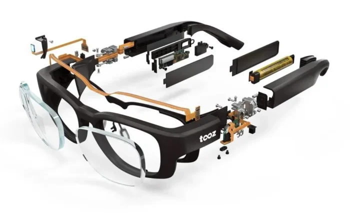
Therefore, FPC technology represents a very important trend in automotive electronics, particularly in smart vehicles, especially in battery BMS, vehicle lighting systems, door control systems, and camera modules.

FPC of auto
Typically, an electric vehicle incorporates over 100 FPCs. Among these, the FPCs used in battery BMS and vehicle camera modules offer the highest application value and represent key areas of development.

BMS FPC
FPC Advantages in Battery Management Systems (BMS)
Regarding the application of FPCs in BMS within battery packs, cost and space are two critical considerations for batteries.
With current technology, battery capacity has essentially reached its limit.
The industry is focused on structural efficiency and maximizing space utilization, yet the size of battery packs is largely fixed.
Consequently, there are inherent limits to how many cells can be accommodated within a pack.
Replacing traditional BMS wiring with FPCs ensures stable performance while reducing the risk of friction between the upper cover and the battery due to expansion and contraction. This has become the mainstream approach across the industry.
In the long term, even the circuits on the main and auxiliary boards could be replaced by chips, which can be mounted on FPCs.
This would maximize product stability, save space, and reduce costs (though currently, there is no significant cost advantage).
Therefore, with every technological iteration, the focus increasingly shifts toward the foundational level.

BMS FPCB
Applications of FPC in New Energy Vehicles
Data acquisition cables are critical components of new energy vehicle BMS systems, enabling the monitoring of voltage and temperature in new energy battery cells; facilitating data collection and transmission while incorporating overcurrent protection; and protecting vehicle battery cells through features such as automatic disconnection in the event of abnormal short circuits.
Previously, data acquisition cables for new energy vehicle power batteries used traditional copper wire harness solutions.
Conventional harnesses consist of copper wires encased in plastic; when connecting to the battery pack, each wire connects to a single electrode.
When the power battery pack generates a large number of current signals, numerous harnesses are required, resulting in significant space consumption.
During the battery pack assembly process, traditional harnesses rely on manual labor to secure terminals to the battery pack, resulting in low automation levels.
Compared to copper wire harnesses, FPCs offer distinct advantages in safety, weight reduction, and neat layout due to their high integration, ultra-thin profile, and exceptional flexibility.
Additionally, because FPCs are thin and allow for customized battery pack structures, they can be directly placed onto the battery pack using robotic arms during assembly, enabling high automation levels and making them suitable for large-scale, high-volume production.
The trend toward replacing copper wire harnesses with FPCs is clear.
FPCs offer the following advantages in power battery modules:
1. High Integration:
Featuring embedded fuses, connectors, chip NTCs, and aluminum/nickel terminals, FPCs not only provide excellent and consistent electrical performance but also meet the design requirements for smaller and higher-density installations.
They enable three-dimensional routing and can adapt their shape to fit spatial constraints, making them suitable for the trend toward high density, miniaturization, and high reliability. This achieves the integration of component assembly and wire connection.
2. Enables automated assembly:
Fast and precise assembly facilitates automation, as it eliminates many errors caused by manual work in traditional wiring harness designs and significantly reduces the risk of incorrect connector insertion.
The use of FPC (Flexible Printed Circuit) reduces the complexity of module integration processes.
The connection between the FPC and the battery busbar can be achieved through automated soldering, effectively reducing labor costs.
Even if customers are unable to implement automated soldering and opt for traditional screw-fastening methods fully, labor costs can still be significantly reduced.
3. Ultra-thin profile:
0.34 mm in the circuit area and 2 mm at the NTC.
4. Exceptional flexibility:
The circuit area supports 90° and 180° bending during assembly.
5. Lightweight:
When used in a vehicle, it can reduce weight by approximately 1 kg compared to a traditional wiring harness solution.
6. Cost Advantage:
From a cost perspective, the FPC itself is not expensive, and it significantly reduces connection costs.
Compared to copper wire harnesses, FPCs offer significant advantages in terms of safety, weight reduction, and neat layout due to their high integration, ultra-thin profile, and exceptional flexibility.
Additionally, because FPCs are thin and battery packs are custom-designed, they can be directly placed onto the battery pack using robotic arms during assembly, enabling a high degree of automation and making them suitable for large-scale, high-volume production.
The trend toward FPCs replacing copper wire harnesses is clear.
| Advantage | Description |
|---|---|
| Safety Performance | While replacing low-current wires, the FPC connects metal tabs to busbars and incorporates a fuse-protection current design. This ensures high-speed signal transmission paths. Even if a battery pack experiences a short circuit, the internal FPC design will directly melt the copper traces, preventing combustion or explosion in other parts of the battery pack. |
| Lightweight Design | Compared with traditional wire harnesses and PCB (Printed Circuit Board) products used for signal collection, FPC occupies less space inside the battery pack and significantly reduces overall weight. |
| Process Flexibility | Compared with traditional wire harnesses that require numerous connection points and complex manual insertion processes, FPC overcomes manufacturing limitations. It can be adapted to the characteristics of the battery pack and supports multiple processes such as ultrasonic welding and soldering. It also offers advantages in thickness (0.34 mm in the circuit area and 2 mm at the NTC area) and flexibility (the circuit area can be bent and assembled at 90° or 180°). |
| Automated Production | FPC has a regular shape and a higher level of design integration, eliminating a large amount of wiring and connection work. It is suitable for large-scale automated manufacturing, greatly shortens assembly time, reduces labor requirements, and provides a foundation for automated production in power battery assembly processes. |
Currently, FPC solutions have become the primary choice for the vast majority of new electric vehicle models. FPCs are integrated into CCS (Cells Contact System, which combines busbars and wiring harness components).
CCS products consist of FPCs, plastic structural components, and copper-aluminum busbars.
The copper-aluminum busbars connect multiple battery cells in series and parallel configurations via laser welding, while the FPCs form electrical connection and signal detection structures by connecting to the busbars and plastic components.

CSS
Composition Materials
1. Insulating Film
The insulating film forms the base layer of the circuit, with an adhesive bonding the copper foil to the insulating layer.
In multi-layer designs, it is further bonded to the inner layers.
These films also serve as a protective cover to isolate the circuit from dust and moisture, and help reduce stress during flexing.
The copper foil forms the conductive layer.
There are many types of insulating film materials, but the most commonly used are polyimide and polyester materials.
Currently, nearly 80% of all flexible circuit manufacturers in the United States use polyimide film materials, while approximately 20% use polyester film materials. Polyimide materials are non-flammable, dimensionally stable, have high tensile strength, and can withstand soldering temperatures.
Polyester, also known as polyethylene terephthalate (PET), has physical properties similar to those of polyimide, with a lower dielectric constant and minimal moisture absorption, but it is not heat-resistant.
Polyester has a melting point of 250°C and a glass transition temperature (Tg) of 80°C, which limits its use in applications requiring extensive edge soldering. In low-temperature applications, it becomes rigid.
Nevertheless, they are suitable for use in products such as telephones and other items that do not need to be exposed to harsh environments.
Polyimide insulating films are typically combined with polyimide or acrylic adhesives, while polyester insulating materials are generally combined with polyester adhesives.
The advantage of combining them with materials that share similar properties is that they maintain dimensional stability after dry welding or after multiple lamination cycles.
Other important properties of the adhesives include a low dielectric constant, high insulation resistance, high glass transition temperature, and low moisture absorption.
2. Conductors
Some flexible circuits incorporate rigid components made of aluminum or stainless steel.
These provide dimensional stability, physical support for the placement of components and conductors, and stress relief.
The adhesive bonds the rigid components to the flexible circuit.
Another material sometimes used in flexible circuits is the adhesive laminate, which is formed by coating both sides of an insulating film with adhesive.
The adhesive laminate provides environmental protection and electrical insulation, eliminates the need for a separate film layer, and enables the creation of multilayer structures with fewer adhesive layers.
Copper foil is suitable for use in flexible circuits and can be produced via electrodeposition (ED) or plating.
Electrodeposited copper foil has a glossy surface on one side, while the processed surface on the other side is dull and matte.
It is a flexible material that can be manufactured in a wide range of thicknesses and widths.
The dull side of ED copper foil is often specially treated to improve its adhesion properties.
In addition to flexibility, rolled copper foil is characterized by its hardness and smoothness, making it suitable for applications requiring dynamic flexing.
3. Adhesives
In addition to bonding insulating films to conductive materials, adhesives can also serve as cover layers, protective coatings, and encapsulating coatings.
The primary difference between the two lies in their application methods: cover-layer adhesives bond insulating films to form laminated circuit structures.
Screen printing technology is used for the adhesive coating. Not all laminated structures include an adhesive; laminates without adhesive result in thinner circuits and greater flexibility.
Compared to adhesive-based laminated structures, they offer superior thermal conductivity.
Due to the thin profile of adhesive-free flexible circuits and the improved thermal conductivity resulting from the elimination of thermal resistance caused by adhesives, they can be used in operating environments where flexible circuits based on adhesive-laminated structures cannot be used.
Basic Structure
Copper Film
Copper Foil: Generally divided into electrolytic copper and rolled copper. Common thicknesses include 1 oz, 1/2 oz, and 1/3 oz.
Substrate Film: Common thicknesses include 1 mil and 1/2 mil.
Adhesive: Thickness is determined by customer requirements.
Cover Film
Cover Film: Used for surface insulation. Common thicknesses are 1 mil and 1/2 mil.
Adhesive: Thickness is determined by customer requirements.
Release Paper: Prevents foreign matter from adhering to the adhesive before lamination; facilitates processing.
Stiffener Film (PI Stiffener Film)
Stiffener Film: Reinforces the mechanical strength of the FPC and facilitates surface mounting operations. Common thicknesses range from 3 mil to 9 mil.
Adhesive: Thickness determined by customer requirements.
Release Paper: Prevents the adhesive from adhering to foreign objects prior to lamination.
EMI: Electromagnetic shielding film, protecting the circuit board’s internal circuits from external interference (in areas with strong electromagnetic fields or prone to interference).
FPC Production Process
| Step | Process |
|---|---|
| 1 | Material Cutting |
| 2 | Inner Layer Circuit Imaging |
| 3 | Lamination |
| 4 | Drilling |
| 5 | PTH (Plated Through Hole) |
| 6 | Copper Plating |
| 7 | Outer Layer Circuit Imaging |
| 8 | Pattern Plating |
| 9 | Etching |
| 10 | Surface Treatment |
| 11 | Dry Film Covering |
| 12 | Pressing |
| 13 | Curing |
| 14 | ENIG (Electroless Nickel Immersion Gold) |
| 15 | Legend Printing |
| 16 | Routing / Profile Cutting |
| 17 | Electrical Testing |
| 18 | Punching |
| 19 | Final Inspection |
| 20 | Packaging |
| 21 | Shipping |
FPC Solutions
Generally, flexible-packaged and rigid-packaged batteries employ different FPC solutions, and implementation methods vary by manufacturer.
This includes different solutions for terminal connectors based on connection methods (crimping, soldering, etc.).
The greatest advantage of FPC lies in its flexibility; as battery control technology evolves, it will take on many forms and is inherently a customized product.

FPC Application
FPC Application in the Automotive Industry
FPC technology was first introduced in 1950, so it is not a new technology from a technical standpoint.
The adoption of FPC technology in automobiles will be as seamless as the integration of other traditional technologies into the automotive sector.
It is never competitors within the same industry that bring about the demise of traditional technologies.
The wiring harness systems in traditional vehicles are complex and cluttered, and the multitude of interfaces imposes complex and costly burdens on vehicle electronic systems.
In the era of smart cars, the computational capabilities of vehicle computers have far surpassed current connection technologies, so the transformation of the underlying infrastructure is merely a matter of time.
Recognizing this, Musk previously introduced a new wiring harness patent technology.
This technology resembles a hybrid between traditional wiring harnesses and FPCs, to maximize the elimination of complex wiring throughout the vehicle and build more advanced electronic systems.

Tesla’s Wiring Harness Patent Technology
Long Flexible Circuits and Smart Harness Development
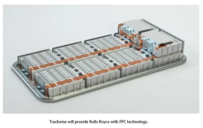
Trackwise initially developed the capability to manufacture length-unlimited, flexible circuits because of a requirement fromRolls Royce.
In an interview with Power Electronics News, Philip Johnston, CEO of Trackwise, said that using long, flexible printed circuits in aircraft could help address the weight and space challenges associated with legacy wiring harnesses
Trackwise long flex is being used for temperature-and voltage-monitoring circuits for electric-vehicle battery packs. In place of a conventional wire harness, flex offers a lighter solution, taking up less space, and potentially for the distribution of control electronics onto a “smart harness.
“With the battery pack in the electric vehicles being the primary energy source, control and monitoring of individual cells and modules are paramount.
This is not only for safety reasons, but also to achieve optimum performance efficiency and themaximum range.
Flexible printed circuits (FPCs) are ideal for use in the control and monitoring circuits of battery modules.
Not only do their compact dimensions offer significant space improvements, but the weight savings are considerable compared tobulky harnesses,” says Johnston.
He added, “Trackwise’s roll-to-roll technology is already being used to manufacture FPCs used in the HV and LV circuits of EV battery modules and packs, reducing assembly time, BOM costs, and saving on space and weight.”

FPC in EV Battery Systems and BMS Applications
Currently, the most common application of FPCs in electric vehicles is in the battery compartment.
After all, battery technology is one of the most critical factors affecting the entire vehicle at this stage.
Improving battery technology to reduce size and lower costs is undoubtedly the most critical objective.
Whether it’s CTP or CTC, as mentioned in the previous article, solutions like CTP battery packs simply eliminate some internal structural components, improve volume utilization, and indirectly boost the system’s energy density.
If solid-state batteries can achieve mass production by 2025—a pivotal year—battery technology will experience rapid advancement.

EV system
Power batteries are generally composed of a pack, modules, and cells. They are typically controlled via a Battery Management System (BMS).
Multiple cells form a module, and the module must monitor the voltage and temperature of the cells.
Traditionally, this was achieved through module sampling harness assemblies.
However, with technological advancements and to meet the demands for efficiency and automation in the mass production of new electric vehicles, integrated buses are now being adopted.
This reduces manual assembly and wiring errors, meets the requirements for highly automated automotive production, and enables voltage acquisition, battery protection, and power transfer between batteries.
Currently, most manufacturers have adopted the FPC+Connector configuration to replace traditional sampling harness assemblies, and FPCs can also monitor the charging process.

FPC+Connector
Industry Supply Chain and Manufacturing Challenges
Currently, every battery manufacturer in China has its own technical solution, and there are many active suppliers, including well-known ones such as Anjieli, Jingwang, Amphenol, Molex, Hengmei, and Guixiang.
Although a detailed comparison of the cost difference between traditional module wiring harness assemblies and FPC assemblies has not been conducted, internal analysis from AVL and data from Amphenol indicate that costs will decrease significantly.
However, as mentioned in previous articles, FPC manufacturing technology remains capital-intensive; it is not an industry where one can simply hire a few people, invest some money, and expect short-term profits.

Exmaple
Actually, from the perspective of module covers, manufacturers with NTC and FPC technology have a slight advantage. It would be even better if they also have expertise in busbar soldering.
Manufacturers with these three technologies—provided they can offer competitive overall costs and reliable performance—will have no trouble securing business under current market conditions.

soft pack
Connectors, on the other hand, are relatively independent components, and there are plenty of manufacturers capable of producing them; the same goes for structural parts—there are plenty of companies that can make them.
NTCs can be purchased off the shelf, and busbar processing plants can handle them. FPC and soldering, however, are two areas that require both cost efficiency and experience.
The key is to identify which manufacturers have a competitive edge in these two areas.

FPC battery pack
Future Outlook of FPC in Smart Vehicles
In the era of smart vehicles, the widespread automated application of FPCs in battery systems is only a matter of time.
In the long run, many low-voltage wiring harness units in vehicles are likely to be gradually replaced as technology advances, especially in an era where vehicles are becoming increasingly intelligent and the requirements for signal interference resistance are becoming increasingly stringent.


