Why Do FPC Flexible Printed Circuits Need Reinforcement?


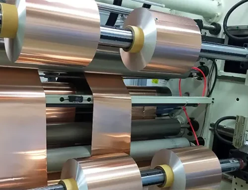
FPCs are widely used in electronic products, but because they have low mechanical strength and are prone to cracking, they require lamination with reinforcing materials to enhance their mechanical strength and facilitate component mounting on the PCB surface.
Today, we’ll take a look at some key information regarding FPC reinforcement.
What is Reinforcement?
While flexible printed circuits (FPCs) are lightweight, thin, and flexible, they lack rigidity.
To add thickness and rigidity to specific areas of the product—facilitating subsequent installation or assembly—a rigid panel is attached to those locations; this process is known as reinforcement.
Reinforcement is a critical step in the FPC manufacturing process and plays a pivotal role in determining the quality of the FPC.

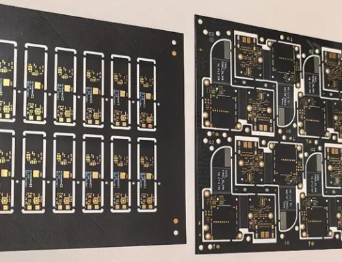
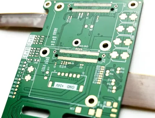
Fig 1
Types of Reinforcement Plates
Stainless Steel Sheets (SS):
Some drawings specify “SUS,” which actually refers to steel reinforcement; “SUS” is a common grade designation for steel sheets.
Specifications: 0.1, 0.2, 0.3, 0.4 mm
Functions: Improves flatness, hardness, heat dissipation, and electrical conductivity/grounding
Aluminum Sheets (AL)
Specifications: 0.1, 0.2, 0.3…2.0 mm
Functions: Increase thickness, improve heat dissipation, and enhance flatness
FR4
Specifications: 0.1, 0.2, 0.3…2.0 mm
Functions: Increase hardness, thickness, and flatness
Polyimide (PI)
Specifications: 0.0275, 0.05, 0.075, 0.1, 0.15, 0.175, 0.2, 0.225, 0.25 mm
Function: Increases thickness.
Polyester (PET)
Specifications: 0.225 mm
Function: Increases thickness.
Auxiliary Materials
Adhesives:
pressure-sensitive adhesives and thermosetting adhesives.
① Pressure-sensitive adhesives:
Double-sided tape for flexible circuits, abbreviated as DST, also known as pressure-sensitive adhesive (PSA);
These can be categorized into standard adhesives, high-temperature-resistant adhesives, conductive adhesives, and thermally conductive adhesives.
Common standard adhesives include 3M 467 and 3M 468; common conductive adhesives include 3M 9703 and 3M 9713;
Thermal adhesives commonly include 3M 8805 and 3M 9882; high-temperature adhesives commonly include 3M 966, 3M 9460, 3M 9077, 3M 9079, and TESA 8853.
② Thermosetting Adhesives:
Abbreviated as TSA, these require curing under high temperature and pressure to achieve bonding.
Thermosetting adhesives are also categorized into standard and conductive types.
| Item | Bonding Strength | Ease of Operation | Time Required |
|---|---|---|---|
| Pressure-Sensitive Adhesive (PSA) | Poor | Simple | Short |
| Thermosetting Adhesive | Good | Complex | Long |
Release paper:
Prevents foreign particles from adhering to the adhesive before lamination.
EMI shielding film:
Protects the circuits on the printed circuit board from external interference (such as strong electromagnetic fields or areas prone to interference).
Differences Between Reinforced Flexible-Rigid Boards and Flexible-Rigid Boards
Similarities: Both consist of flexible and rigid materials bonded together with an adhesive layer.
Differences: In rigid-flex boards, the rigid substrate contains circuit traces, and the traces on the flexible substrate are electrically connected to those on the rigid substrate via vias.
In contrast, on a flexible substrate with a reinforcement plate attached, the rigid substrate typically has no traces—not even pads.
The flexible and rigid substrates are connected only mechanically, with no electrical connection.
Of course, some specialized reinforcement plates may include pads or optical points, but these pads are not electrically connected to the traces on the flexible substrate.
Design Considerations for FPC Reinforcement
The design of reinforcement structures must be carefully planned to meet both mechanical and assembly requirements.
One of the most important considerations is reinforcement thickness.
The selected thickness must match the final application, especially in connector areas where dimensional accuracy is critical. Improper thickness selection can lead to poor connector engagement or assembly difficulties.
Reinforcement is often added beneath components such as connectors, integrated circuits, switches, LEDs, and shielding structures.
These components require a stable mounting surface that minimizes flexing during assembly and operation.
By increasing rigidity in these areas, reinforcement helps improve solder joint reliability and overall product durability.
Engineers must also pay close attention to bending areas when designing reinforced FPCs.
Reinforcement materials should generally not extend into dynamic flex regions because excessive stiffness can concentrate stress and reduce flex life.
Improper reinforcement placement may lead to copper trace cracking, coverlay separation, or premature mechanical failure during repeated bending cycles.
Common Quality Issues in Reinforcement Processing
Although reinforcement technology is relatively mature, several manufacturing defects can still occur if process controls are not properly maintained.
One common issue is reinforcement misalignment, which may result from inaccurate positioning during lamination.
Even small alignment deviations can affect connector installation and component placement accuracy.
Air bubbles are another frequent concern. Dust contamination, insufficient lamination pressure, or improper processing conditions can trap air between the reinforcement and the FPC.
These voids not only affect appearance but can also reduce bonding strength and long-term reliability.
Delamination is a more serious defect that occurs when the reinforcement separates from the flexible circuit.
This problem is often caused by inadequate curing conditions, adhesive incompatibility, or poor surface preparation.
In addition, excessive thermal stress during manufacturing may lead to warpage, causing flatness issues that complicate assembly and reduce product quality.
Reliability Testing of Reinforced FPCs
To ensure reliable performance in demanding environments, reinforced FPCs are subjected to a variety of qualification tests.
Peel strength testing is commonly performed to evaluate the bonding force between the reinforcement plate and the flexible substrate.
Strong adhesion is essential for maintaining structural integrity throughout the product’s service life.
Thermal testing is also critical because electronic products are frequently exposed to changing environmental conditions.
Thermal shock testing evaluates the ability of the bonded structure to withstand rapid temperature transitions, while high-temperature storage testing verifies long-term material stability under elevated temperatures.
For products that experience repeated movement, bending life testing is used to assess durability under continuous flexing conditions.
In addition, soldering heat resistance testing ensures that the reinforcement structure can withstand the high temperatures encountered during SMT reflow assembly without experiencing deformation or delamination.
Applications of Reinforced FPCs
Reinforced FPC technology has become an essential solution across numerous industries due to its ability to combine flexibility with localized rigidity.
In consumer electronics, reinforced FPCs are widely used in smartphones, tablets, wearable devices, cameras, and wireless earphones, where compact designs require both flexibility and mechanical support.
The automotive industry also relies heavily on reinforced flexible circuits for instrument clusters, infotainment systems, camera modules, and advanced driver-assistance systems.
In medical devices, reinforced FPCs provide reliable interconnections for portable diagnostic equipment, patient monitoring systems, and wearable healthcare products.
Industrial automation systems, robotics, aerospace electronics, and communication equipment further benefit from reinforced FPC structures because they offer improved durability, dimensional stability, and resistance to harsh operating conditions.
Conclusion
Reinforcement technology is a fundamental aspect of modern FPC manufacturing.
By integrating materials such as FR4, stainless steel, aluminum, polyimide, or PET into selected areas of a flexible circuit, manufacturers can significantly improve mechanical strength, assembly performance, and product reliability.
Successful reinforcement requires careful material selection, precise lamination processes, appropriate adhesive systems, and rigorous quality control.
As electronic products continue to evolve toward thinner, lighter, and more highly integrated designs, reinforcement technology will remain a key enabling factor in the development of advanced flexible electronic solutions.