
FPC Laminate Design: The Layering Secrets Behind Foldable Phone Flexibility
FPC Laminate Design is the layer arrangement inside a flexible printed circuit. It defines how the circuit bends, carries signals, and survives repeated folding. For foldable phones, the stackup and neutral axis often decide whether a hinge FPC lasts. This guide explains the core choices without marketing hype.
What Is FPC Laminate Design?
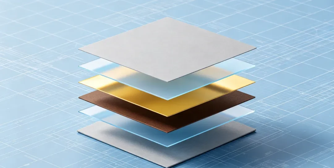
FPC Laminate Design describes how copper, dielectric, and protective layers are combined into a flexible circuit. The base material is often FCCL, or flexible copper clad laminate. During lamination, heat and pressure bond these layers into one bendable structure. Therefore, the design controls both electrical performance and mechanical endurance.
Core Layers in a Typical Flex Laminate
A flex laminate usually includes a conductive copper layer and a dielectric layer. It also has a protective layer and a surface finish on exposed pads. In addition, the FCCL base provides the starting copper and dielectric combination. Each layer affects bend behavior and signal quality.
FPC Stackup Design for Foldable Phones

Flip Phone Hinge FPC
FPC stackup design for foldable phones focuses on the bend zone. In a foldable, the display and hinge area must flex repeatedly. Therefore, the stackup should keep the bend region thin and balanced. For example, Gekun’s Flip Phone Hinge FPC uses a flexible stackup for hinge motion. This approach helps reduce stress on the outer layers.
Layer Count and Symmetry
Layer count affects stiffness. A balanced stackup places similar materials above and below the conductor. Also, a symmetrical build reduces warping during lamination. As a result, the flex circuit bends more predictably.
Neutral Axis Design in FPC
Neutral axis design in FPC places the copper traces near the zero-strain plane. When a flex circuit bends, the outer layers stretch and the inner layers compress. The neutral axis sits between them, where strain is lowest. Therefore, keeping conductors close to this axis improves bend life.
Why It Matters for Foldable Hinges
For foldable hinges, the neutral axis moves as the phone opens and closes. However, a well-designed stackup limits that movement. In addition, thin dielectric layers can bring the copper closer to the neutral axis. This reduces the risk of conductor fatigue.
Material and Layer Choices in FPC Laminate Design
Material choice sets the foundation of FPC Laminate Design. FCCL provides the conductive copper and dielectric base. The surface finish protects exposed copper and supports assembly. Also, the flex material must match the bend radius and thermal needs. Therefore, review the flex material before finalizing the stackup.
Copper, Dielectric, and Surface Finish
The copper layer carries signals and power. The dielectric layer separates copper layers and controls impedance. The surface finish protects pads during storage and soldering. In addition, the lamination process bonds these layers under heat and pressure.
Manufacturing Steps That Affect FPC Laminate Reliability
FPC Laminate Design only works if manufacturing matches the intent. The lamination process controls layer bonding and thickness. Next, drilling creates vias and holes for connections. Copper plating then builds conductive paths. After that, etching defines the circuit pattern.
Adhesion and Inspection
Nickel–copper adhesion failure can cause open circuits or intermittent signals. Therefore, tests should check adhesion and hole wall quality. For example, PCB hole wall quality inspection looks for defects after drilling and plating. Also, the right surface finish helps prevent oxidation.
How to Review an FPC Stackup Before Production
Start by marking every bend zone in the design. Then place the neutral axis near the copper traces. Next, choose materials that match the bend and thermal requirements. Finally, confirm the stackup with testing and a manufacturing review.
Checklist for Foldable and Hinge FPCs
- Identify static and dynamic bend areas.
- Balance layer count above and below the conductors.
- Keep the bend zone free of unnecessary plating or stiff layers.
- Review FCCL, surface finish, and lamination process.
- Test adhesion, hole wall quality, and bend performance.
FAQ
What is FPC Laminate Design?
FPC Laminate Design is the arrangement of copper, dielectric, and protective layers in a flexible printed circuit. It determines bend performance, signal integrity, and reliability. For foldable phones, the stackup and neutral axis are central to the design.
Why is neutral axis design in FPC important for foldable phones?
Neutral axis design in FPC keeps copper traces near the low-strain plane during bending. This placement reduces stress on conductors as the hinge opens and closes. Therefore, it helps extend flex life in foldable phone hinges and display FPCs.
How does FPC stackup design for foldable phones differ from standard flex?
FPC stackup design for foldable phones prioritizes the dynamic bend zone. It often uses a balanced, symmetrical layer build. In addition, it places the neutral axis near the copper and controls thickness. Standard flex may not need this level of bend optimization.
Which Gekun products relate to FPC Laminate Design for foldables?
Gekun offers Flip Phone Hinge FPC, Display FPC, Side Key FPC, Sensor FPC, Transfer FPC, and Ultra-Long Flex PCB. The company also builds rigid-flex PCB and flex PCB assemblies. Gekun has been a flexible PCB manufacturer since 2014. Contact Gekun for flex PCB fabrication quotes.
Related Posts
- FPC Design Guide — Related article
- Rigid-Flex PCB Design Guide — Related article
- Design of Automatic Assembly Equipment for Flexible Circuit Board — Related article
- FPCB Bump Cracking Guide — Related article
- Flexible PCB Design Mistakes to Avoid | Gekun FPC Guide — Related article





