FPCs for Power and Energy Storage Systems: Manufacturing Processes, Technical Requirements, and Industry Evolution

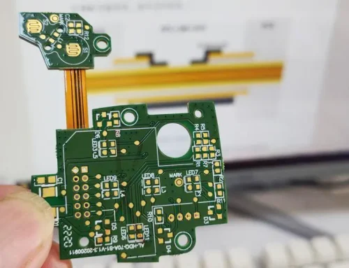
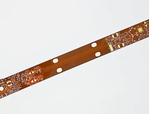
Flexible Printed Circuits (FPCs) used in power systems and energy storage applications play a foundational role in new energy vehicles (NEVs) and battery energy storage systems (ESS). Unlike consumer electronics FPCs, these are not simply interconnect components—they function as critical sensing and signal transmission networks inside battery packs.
They are widely used for voltage sampling, temperature monitoring, and data communication within battery modules, often replacing traditional BMS sampling harnesses or flat flexible cables (FFCs).
Because they operate in high-voltage, high-current, and high-vibration environments—and must also withstand potential thermal runaway scenarios—these FPCs demand extremely high levels of safety, reliability, and durability.
This article outlines their core manufacturing processes, highlights key technical requirements, and explains how they differ fundamentally from standard consumer-grade FPCs.
Special Requirements for Power and Energy Storage FPCs
Before discussing manufacturing processes, it is essential to understand the unique engineering constraints that define material selection and process design.
High Voltage and High Current Capability
These FPCs must operate reliably under system voltages up to 800V or higher and support strong current-carrying capacity without overheating or degradation.
Exceptional Safety and Reliability
The design must eliminate risks of open circuits and short circuits. High insulation resistance, strong dielectric strength, and excellent arc resistance are mandatory.
Thermal and Environmental Resistance
Operating conditions typically range from -40°C to 125°C or higher. The materials must also endure thermal cycling, humidity exposure, and long-term aging without performance drift.
Electrolyte Corrosion Resistance
Inside battery packs, electrolyte leakage (e.g., LiPF₆-based systems) may occur. FPC materials must resist chemical corrosion and maintain structural integrity over long service life.
Mechanical Balance: Strength vs Flexibility
While certain regions require rigidity for mounting and connector stability, other areas must remain flexible to accommodate vibration, thermal expansion, and cell swelling.
Flame Retardancy
Materials must comply with high flame-retardant standards (such as UL94 V-0) to prevent fire propagation in extreme failure conditions.
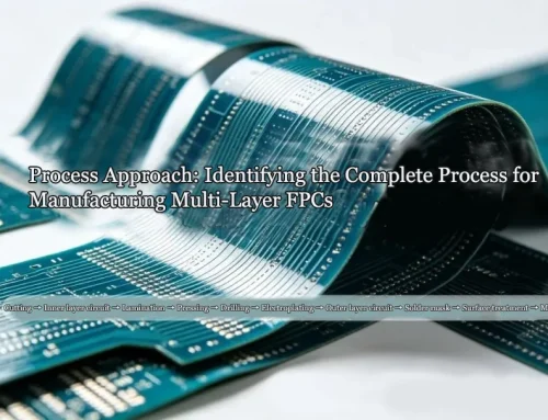
Core Manufacturing Process Flow
The production of power-grade FPCs follows a highly controlled sequence:

Manufacturing Process Flow
Key Process Breakdown
Material Selection (Foundation of Reliability)
Engineers determine material selection as the factor that sets the fundamental performance ceiling of the entire product.
In power and energy storage FPCs, designers closely tie material choice to thermal stability, electrical safety, and long-term mechanical endurance.
The base substrate typically uses polyimide (PI) films, often in thicker gauges such as 25μm, 50μm, or above.
The increased thickness is not simply for strength; it plays a key role in improving dimensional stability under thermal cycling and maintaining structural integrity in high-temperature environments.
Engineers generally prefer rolled annealed (RA) copper over electro-deposited (ED) copper for conductive layers.
The reason lies in its superior fatigue resistance under repeated bending and vibration, which is critical in automotive battery environments.
Engineers select copper thickness based on current requirements, typically in the range of 1 oz (35μm) to 2 oz (70μm), particularly for high-current pathways.
Material specialists design coverlay systems and adhesive layers with a strong emphasis on chemical and thermal resilience.
High-performance polyimide-based cover films, combined with adhesives resistant to heat and electrolyte corrosion, ensure stable insulation performance throughout long service life inside battery packs.
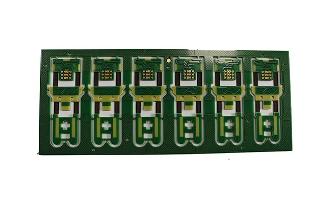
In structurally critical regions such as connector interfaces and mounting zones, reinforcement materials are introduced.
These may include FR4, aluminum sheets, stainless steel, or thicker PI layers, each selected according to mechanical load and assembly requirements.
To complete the system, flexible solder mask inks are applied to enhance insulation and provide an additional layer of environmental protection.
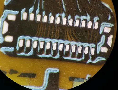
Circuit Pattern Formation (Core Fabrication)
This stage defines the electrical architecture of the FPC and directly determines its functional integrity.
Operators begin the process by cutting panels and forming vias, using laser drilling or precision mechanical drilling depending on design complexity and required resolution.
Technicians then deposit copper through electroless and electrolytic plating processes to ensure reliable electrical interconnection, particularly within vias.
At this stage, uniformity of deposition and adhesion strength are critical factors influencing long-term reliability.
A photosensitive dry film is subsequently applied to the copper surface and exposed using Laser Direct Imaging (LDI).
This enables high-resolution transfer of circuit patterns with tight dimensional control. After exposure, the development process removes unexposed areas, and chemical etching eliminates excess copper to form precise conductive traces.
After completing patterning, operators strip the protective film and perform 100% Automated Optical Inspection (AOI).
This ensures early detection of defects such as opens, shorts, or pattern deviations before the process advances to subsequent stages.
Coverlay Lamination
Technicians precisely align pre-patterned coverlay films with the circuit and laminate them under controlled temperature and pressure conditions in this stage.
Although the process appears straightforward, it is highly sensitive to process parameters.
Temperature uniformity, pressure distribution, and curing time all directly influence adhesion strength, insulation reliability, and long-term resistance to delamination.
Surface Finishing
Surface finishing serves two primary functions: protecting exposed copper from oxidation and ensuring stable solderability and electrical contact performance.
Engineers in high-reliability applications most widely adopt ENEPIG (Electroless Nickel Electroless Palladium Immersion Gold) among the available surface finishing options.
It provides a robust diffusion barrier, excellent corrosion resistance, and highly stable solder joint performance.
Manufacturers apply hard gold plating to contact-intensive areas such as connectors because it provides superior wear resistance.
Cost-sensitive applications sometimes use OSP (Organic Solderability Preservative), but engineers generally avoid it in automotive-grade environments due to its limited durability.
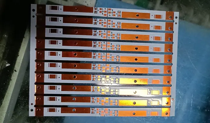
Reinforcement Lamination
Reinforcement structures are laminated onto designated mechanical zones using controlled high-temperature pressing processes.
This step is critical for ensuring structural rigidity in connector areas and mounting points.
Proper process control ensures precise alignment, strong adhesion, and elimination of voids or air entrapment, which could otherwise compromise mechanical stability.
Printing and Marking
Printing processes provide both functional protection and manufacturing traceability. Flexible solder mask ink is applied to non-soldering regions to enhance insulation and environmental resistance.
In addition, component markings such as part numbers, polarity indicators, revision codes, and traceability identifiers are printed onto the surface. These markings play an important role in assembly control and lifecycle traceability within automotive systems.
Electrical Testing and Profiling
Before final release, every unit undergoes full electrical verification.
Technicians use flying probe systems or dedicated fixtures to confirm continuity and insulation performance across the entire circuit, ensuring zero defects in electrical functionality.
Manufacturers carry out profiling using laser cutting or die cutting, selecting the method based on production volume and design complexity.
Laser cutting provides high precision with minimal mechanical stress, while die cutting offers efficiency advantages in mass production environments.
After profiling, thorough cleaning is performed to remove any residual particles or conductive debris generated during cutting, preventing potential contamination risks.
Final Inspection and Packaging
The final quality control stage combines visual inspection, dimensional verification, and structural assessment.
Quality inspectors carefully review surface defects, contamination, and reinforcement alignment while they measure critical dimensions against strict tolerances.
Packaging engineers design packaging specifically for high-reliability transportation environments.
Manufacturers use anti-static, moisture-resistant, and deformation-resistant materials, and they secure products in individual trays or carriers to prevent mechanical stress during shipping.