
Flex PCB Stiffener Materials and Functions

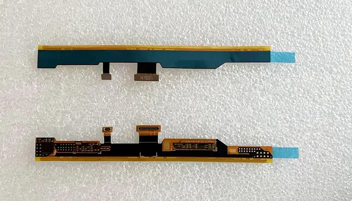
Flexible printed circuit boards (FPCBs) are widely valued for their ability to bend, fold, and adapt to compact electronic architectures. However, in real engineering environments, flexibility alone is not sufficient for reliability.
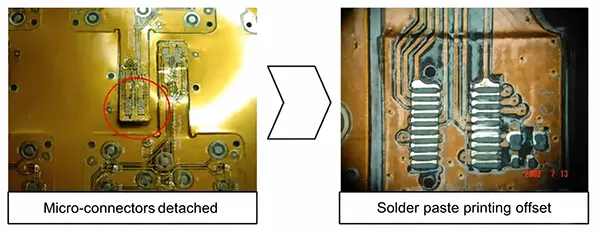
Most field failures in flex assemblies do not originate from the flexible region itself, but from mechanically weak transition zones—especially around connectors, component pads, and solder joints.
Industry reliability studies and assembly failure reports consistently show that a significant portion of flex-related defects occur during assembly and solder reflow stages, where temporary mechanical stress exceeds the elastic limit of copper traces or adhesive systems.
This is why almost every production-grade flex PCB design includes a PCB stiffener—a seemingly simple addition that plays a decisive role in product survival.
This article explains stiffeners not as optional accessories, but as engineered mechanical control layers that define the reliability envelope of flex circuits.
Paradox of Flexible Electronics: Flexible, but Not Fragile
The core contradiction in flex PCB design is straightforward: while the substrate is designed for bending, the functional components are not.
A typical flex PCB consists of copper traces laminated on polyimide films, which have excellent flexibility but relatively low mechanical stiffness (flexural modulus significantly lower than FR-4 rigid substrates).
When components such as connectors or BGAs are mounted directly on these flexible regions, the mechanical mismatch becomes critical.
In real production environments, three recurring failure modes dominate:
- Connector lift or deformation during insertion cycles
- Pad cracking or copper fatigue under bending stress
- Reflow-induced warping leading to component misalignment
These issues are not theoretical—they are widely documented in flex assembly failure analyses across consumer electronics, automotive electronics, and medical devices. IPC-2223 guidelines explicitly highlight the need for mechanical reinforcement in areas subjected to concentrated stress.
The key engineering insight is simple:
Flexibility must be selectively constrained to ensure functional stability.
This is where stiffeners become essential.
What a PCB Stiffener Really Does (Beyond “Support”)
A PCB stiffener is commonly described as a reinforcement layer, but this definition is too superficial for engineering use.
A more accurate interpretation is that a stiffener is a localized mechanical modulus control layer bonded to specific regions of a flexible circuit.
Unlike copper or dielectric layers, stiffeners do not contribute to electrical performance.
Instead, they modify the mechanical response of the structure—specifically stiffness (EI), stress distribution, and deformation behavior.
From a structural mechanics perspective, adding a stiffener increases the local moment of inertia, thereby reducing bending strain in critical regions.
Engineering Reality: Mechanical Control, Not Simple Reinforcement
When a stiffener is bonded to a flex PCB, it does not simply “strengthen” the area. It fundamentally changes how stress flows through the structure.
Finite element analysis (FEA) models in rigid-flex design studies consistently show that properly designed stiffeners can reduce peak strain in copper traces by 20–40% in high-stress zones, depending on material and thickness selection.
This reduction is often the difference between long-term reliability and early fatigue failure.
In other words, stiffeners act as mechanical boundary controllers, not passive reinforcements.
Core Functional Roles of Stiffeners
Rather than viewing stiffeners as a single-purpose feature, they should be understood through three engineering functions:
1. Stress Redistribution
Without stiffeners, mechanical stress concentrates at connector pads, bend edges, and transition zones. A stiffener spreads these loads across a larger area, reducing localized strain peaks that lead to cracking or delamination.
2. Assembly Stabilization
During automated SMT assembly, flexible circuits tend to deform under pick-and-place pressure and stencil loading. Stiffeners ensure planar stability, improving placement accuracy and reducing solder defects such as tombstoning or bridging.
3. Interface Conditioning
Connectors such as ZIF or board-to-board interfaces require strict dimensional tolerances. Stiffeners ensure consistent thickness, flatness, and insertion force behavior, directly influencing electrical contact reliability.
Key Insight: Mechanical Firmware for Flex Circuits
A useful engineering analogy is to think of stiffeners as “mechanical firmware” embedded into a flex PCB system.
Just as firmware controls how electronic hardware behaves, stiffeners control how a flexible structure responds to physical forces.
They define where the board is allowed to bend—and more importantly, where it must not.
Where Stiffeners Decide Product Success (Failure-Driven View)
In practical manufacturing, stiffeners are not optional enhancements—they directly determine whether a product passes or fails at multiple lifecycle stages.
These stages can be categorized into three distinct stress environments.
Manufacturing Stage: SMT and Reflow Stability
During SMT assembly, flexible circuits face mechanical instability that rigid PCBs do not experience. The lack of structural rigidity leads to:
- Misalignment during pick-and-place operations
- Stencil collapse or uneven solder paste deposition
- Component “floating” during reflow due to substrate warping
Reflow soldering introduces thermal gradients exceeding 200°C, which further exacerbates deformation in unsupported flex regions. Without stiffeners, localized warpage can cause open joints or solder bridges.
Empirical manufacturing data from flex assembly lines shows that adding localized FR-4 or polyimide stiffeners can significantly improve first-pass yield by stabilizing the assembly surface.
Assembly Stage: Connector Integrity and Dimensional Control
The assembly stage is where stiffeners have the most visible mechanical impact.
Connectors such as ZIF interfaces require strict thickness tolerances, often within ±0.05 mm. Without a stiffener, the flex tail may deform under insertion force, leading to:
- Poor electrical contact pressure
- Increased insertion failure rate
- Long-term wear of contact fingers
In addition, misalignment during assembly is a common issue when flexible tails are unsupported. Even slight angular deviation can result in intermittent signal failure.
A properly designed stiffener ensures that the connector interface behaves like a rigid PCB section, while the rest of the circuit remains flexible.
Field Operation Stage: Fatigue and Environmental Stress
Once deployed, flex PCBs are subjected to continuous mechanical and environmental stress:
- Repeated bending cycles
- Vibration in automotive and industrial systems
- Thermal expansion and contraction cycles
The most critical failure mechanism in this stage is copper trace fatigue near rigid-flex transition zones. These zones experience abrupt stiffness changes, creating stress concentration points.
Stiffeners mitigate this by smoothing mechanical transitions and reducing strain gradients. In high-reliability applications, such as automotive electronics, this is essential for meeting long-term fatigue requirements.
Concept Summary: The 3-Life-Cycle Stress Zones
Across all stages, flex PCB failure can be understood through a unified model:
- Manufacturing Stress Zone → assembly and reflow instability
- Assembly Stress Zone → connector and alignment precision
- Operational Stress Zone → bending fatigue and vibration
Stiffeners function as the primary design tool for controlling all three zones simultaneously.
Classification of Stiffener Materials (Re-Engineered View)
In flex PCB engineering, material selection is often oversimplified into “which stiffener is used where.” In reality, stiffener materials behave as mechanical response systems, not just static supports.
A more accurate classification is based on mechanical behavior families, defined by stiffness contribution, thermal stability, and structural integration capability.
This approach is closer to how reliability engineers evaluate flex assemblies: not by material name, but by how the material behaves under thermal-mechanical cycling, assembly stress, and long-term fatigue loading.
“Soft Stabilizers” (Low Rigidity, High Flex Harmony)
Soft stabilizers are designed to introduce controlled local constraints without fundamentally altering the flexibility of the circuit. They are typically used in cost-sensitive and highly compact consumer applications where full structural rigidity is not required.
PSA / Adhesive Films
Pressure-sensitive adhesive (PSA) systems function primarily as interface dampers rather than structural reinforcements. Their mechanical contribution is modest but strategically important in low-load regions.
Mechanically, PSA layers provide:
- Vibration damping between layers
- Minor reinforcement against local buckling
- Temporary planar stabilization during assembly
However, their polymeric nature introduces time-dependent deformation behavior (creep), especially under elevated temperature.
PET (Polyethylene Terephthalate)
PET-based stiffeners are generally considered temporary structural supports. They are widely used in low-cost electronics where mechanical loading is minimal.
Their primary limitation is thermal incompatibility with solder reflow processes. Standard lead-free assembly profiles (~245–260°C peak) exceed PET’s glass transition stability range, resulting in shrinkage and dimensional instability.
Key Behavior Summary
| Material | Mechanical Role | Thermal Compatibility | Reliability Behavior |
|---|---|---|---|
| PSA | Damping + light support | Medium–Low | Aging & creep sensitive |
| PET | Temporary rigidity | Poor (reflow risk) | Dimensional instability |
Soft stabilizers are therefore best understood as process enablers, not long-term structural elements.
“Engineering Plastics” (Balanced Performance Core)
Polyimide (PI)
Polyimide stiffeners represent the engineering equilibrium point in flex PCB design. Unlike FR-4 or metals, PI does not rely on high rigidity; instead, it provides exceptional thermal stability and dimensional consistency under stress.
In high-end flex systems, PI is frequently the default choice for:
- ZIF connector thickness control
- SMT pad reinforcement in thermal cycling environments
- Wear-resistant flex regions
- High-reliability consumer and industrial electronics
A critical misconception is that PI functions as a “moderately stiff material.” In engineering terms, its key value is not stiffness but predictable elastic behavior across temperature cycles.
This is why PI is often preferred in applications where reflow stability and dimensional tolerance are more important than absolute rigidity.
Key Insight
Polyimide is not chosen because it is stiff—it is chosen because it is stable.
“Structural Rigidizers” (Load-Bearing Materials)
FR-4
FR-4 represents the true structural backbone class of stiffeners. It is a glass-reinforced epoxy composite designed for high mechanical strength and excellent thermal resistance.
When applied to flex circuits, FR-4 fundamentally changes the mechanical nature of the region, effectively transforming it into a semi-rigid functional module.
Typical applications include:
- High-pin-count connector regions
- Through-hole component mounting zones
- Areas requiring rigid insertion behavior
However, this transformation comes with a cost: localized elimination of flexibility. Once FR-4 is introduced, bending capability is effectively removed in that region.
Mechanical Trade-Off
| Property | Impact of FR-4 |
|---|---|
| Rigidity | Very high |
| Flexibility | Eliminated locally |
| Thermal resistance | Excellent |
| Assembly stability | High |
FR-4 is therefore not a “support material,” but a structural redesign decision.
“Extreme Reinforcement Materials”
Aluminum
Aluminum stiffeners introduce a dual-function behavior: mechanical reinforcement + thermal spreading.
This makes aluminum particularly effective in:
- LED flex lighting systems
- Power electronics flex interconnects
- High thermal flux regions
Its thermal conductivity provides localized heat dissipation, reducing hotspot accumulation. However, this also introduces design complexity due to thermal expansion mismatch with polymer substrates.
Stainless Steel
Stainless steel represents the maximum mechanical reinforcement category in flex PCB design. It is used in environments where mechanical abuse, insertion force, or structural protection is the primary concern.
Common applications include:
- Ultra-high insertion force connectors
- Rugged industrial or automotive interfaces
- Mechanical protection zones under repeated stress
However, stainless steel introduces two major engineering risks:
- Electrical insulation failure risk if isolation layers are insufficient
- Significant stiffness discontinuity, which can amplify edge stress concentration
Comparative Behavior Overview
| Material | Primary Function | Advantage | Engineering Risk |
|---|---|---|---|
| Aluminum | Stiffness + heat spreading | Thermal management | Expansion mismatch |
| Stainless Steel | Maximum protection | Extreme durability | Insulation + stress concentration |
Material Selection Is Not a Choice — It’s a Trade-Off Equation
Selecting a stiffener material is not a preference decision. It is a multi-variable constraint optimization problem, where mechanical, thermal, and integration requirements must be balanced simultaneously.
“3D Constraint Model”
A practical engineering model for stiffener selection can be defined using three dominant constraint dimensions:
1. Temperature Constraint
This includes:
- Reflow temperature exposure (~245–260°C in lead-free assembly)
- Long-term operating temperature cycling
- Thermal shock resistance
2. Mechanical Constraint
This includes:
- Bending radius requirements
- Connector insertion force
- Vibration and fatigue loading
3. Integration Constraint
This includes:
- Available stack-up thickness
- Connector dimensional requirements
- Assembly process compatibility
These three constraints define the feasible material space.
Simple Mapping Logic (Engineering Heuristic)
While real designs require simulation and validation, industrial practice often follows a constrained heuristic model:
| Application Requirement | Preferred Material |
|---|---|
| High temperature + precision tolerance | Polyimide (PI) |
| High structural load + rigidity | FR-4 |
| Thermal dissipation + power density | Aluminum |
| Extreme mechanical protection | Stainless Steel |
| Cost-sensitive + non-critical region | PET / PSA |
This mapping is not absolute, but it reflects industry-first-order decision logic used in early design phases before detailed FEA validation.
Hidden Design Variable Most Engineers Ignore: Stiffener Edge Stress
While material selection dominates design discussions, real-world failures frequently originate elsewhere: the interface between stiffener and flexible substrate.
Why Failures Occur at Edges
Stiffener edges introduce abrupt changes in mechanical modulus. This creates localized stress amplification zones, which are the primary origin points for:
- Delamination between adhesive layers
- Micro-crack initiation in copper traces
- Fatigue propagation under cyclic bending
From a fracture mechanics perspective, this is a classic case of stress concentration at material discontinuity boundaries.
Engineering Mitigation Strategies
Effective designs do not eliminate stiffener edges—they engineer the stress transition zone.
1. Edge Overlap (Mechanical Gradient Design)
Extending stiffener slightly beyond component footprints helps distribute stress over a larger area, reducing peak strain concentration.
2. Radius Optimization
Sharp corners act as stress multipliers. Introducing fillets or curved transitions reduces crack initiation probability by smoothing strain gradients.
3. Adhesive Flow Control
Controlling adhesive thickness and flow prevents void formation and ensures uniform load transfer across the interface.
Key Engineering Insight
The stiffener itself is rarely the failure point. The failure originates at the transition boundary where stiffness changes abruptly.
This insight is critical because it shifts the design focus from “material selection” to interface engineering, which is often the true determinant of long-term reliability.
Below is a professional continuation of your blog, written in a technical, publication-ready style, with engineering reasoning, structured tables, and industry-grounded terminology, while avoiding excessive bulleting and keeping a narrative flow.
Stiffener Placement Strategy (Not Just Positioning, but System Design)
In mature flex PCB design, stiffener placement is not treated as a geometric afterthought. It is a mechanical system design decision, where each region of the circuit is assigned a different structural role depending on how it interacts with stress, assembly forces, and long-term fatigue.
Rather than “where to place reinforcement,” the correct engineering question is:
“How should stiffness be distributed across functional zones of the product lifecycle?”
This shift in thinking is critical because most flex PCB failures do not originate from material selection—they originate from incorrect mechanical zoning.
Functional Zones in Flex PCB Architecture
A flex circuit can be logically divided into four mechanical-functional zones, each with distinct stress characteristics and stiffener requirements.
The connector zone is the most mechanically constrained region. It experiences insertion force, contact pressure, and strict dimensional tolerances. In this region, stiffeners are not optional—they define whether electrical contact remains stable under repeated mating cycles.
The component zone behaves differently. Here, stiffeners function primarily as assembly stabilizers, ensuring flatness during SMT placement and reflow. Mechanical rigidity is required, but not necessarily long-term load-bearing capacity.
The bend zone is the most mechanically sensitive region in the entire system. Any stiffener intrusion here must be carefully avoided or minimized. Even small stiffness gradients can significantly increase strain concentration, accelerating copper fatigue.
The transition zone, where rigid and flexible sections meet, is often the most failure-prone area in real applications. This region experiences abrupt modulus changes, making it highly susceptible to delamination and crack propagation if not properly designed.
Smart Placement Logic: From Geometry to Mechanical Field Control
Advanced stiffener design is increasingly treated as a stress-field management problem, rather than a placement problem.
One of the most important strategies is asymmetric stiffening, where reinforcement is applied unevenly to counteract directional stress. This is particularly effective in designs where connectors or components introduce unbalanced loading conditions during operation.
Another emerging approach is dual-layer stiffening, where both top and bottom reinforcement layers are used in complementary zones. This technique improves resistance to multi-axis loading, especially in vibration-heavy environments such as automotive ECUs or industrial sensors.
A third critical decision is the trade-off between partial reinforcement and full reinforcement. Partial reinforcement is often preferred in modern compact electronics because it allows controlled flexibility while still protecting high-risk zones. Full reinforcement, while mechanically robust, often eliminates design freedom in packaging.
Manufacturing Reality: What Designers Usually Get Wrong
Even well-optimized stiffener designs often fail during manufacturing due to a mismatch between design assumptions and fabrication realities. This gap is one of the most underestimated risks in flex PCB engineering.
One of the most common issues is misalignment tolerance accumulation. While CAD models assume perfect registration between stiffener and flex layers, actual manufacturing introduces stack-up tolerances that can lead to slight but critical offsets. These small deviations are often enough to create uneven stress distribution or partial pad coverage.
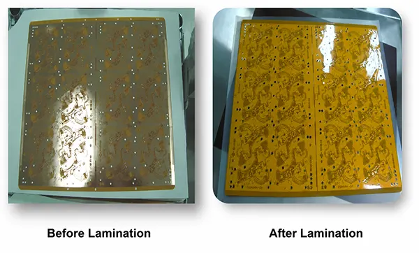
Another frequent failure mode is adhesive squeeze-out, where excess bonding material flows beyond the intended boundary during lamination. This can interfere with nearby traces, reduce effective bending flexibility, or create unpredictable stiffness gradients.
Thermal processes introduce additional complexity. During reflow soldering, thermal expansion mismatch between stiffener and polyimide substrate can trigger localized delamination, especially in FR-4 or metal-reinforced designs where CTE differences are significant.
Mechanical stack-up issues also play a role. When stiffener thickness is not properly matched with solder paste stencil height or connector geometry, it can result in inconsistent solder joint formation or connector misfit.
Finally, panelization strategy significantly affects accuracy. Large production panels may introduce slight warpage or alignment drift, which accumulates across stiffener regions, especially in high-density designs.
Key Engineering Insight: Design Intent vs Fabrication Reality Gap
In flex PCB systems, failure is rarely caused by incorrect theory—it is caused by unverified manufacturing translation.
Bridging this gap requires early collaboration between design engineers and fabrication engineers, particularly during stack-up definition and stiffener layout planning.
Stiffener vs Rigid-Flex: The Strategic Decision Point
At system level, engineers are often faced with a fundamental architectural choice:
Should the design use flex PCB with stiffeners, or transition to rigid-flex construction?
These two approaches are not interchangeable—they represent different engineering philosophies.
A flex PCB with stiffeners relies on localized reinforcement. Flexibility is preserved globally, while rigidity is introduced only where needed. This makes it ideal for cost-sensitive designs and applications where bending is required only in limited regions.
A rigid-flex PCB, on the other hand, is a system-level integration approach. It eliminates interconnect points between rigid sections and replaces them with continuous internal electrical routing. This significantly improves reliability but increases manufacturing complexity and cost.
From a performance perspective, rigid-flex offers higher integration density and fewer failure points. However, flex with stiffeners often provides a better balance between cost, manufacturability, and mechanical performance in mid-complexity systems.
Strategic Comparison
| Criterion | Flex + Stiffener | Rigid-Flex |
|---|---|---|
| Mechanical Strategy | Local reinforcement | System integration |
| Cost | Lower | Higher |
| Reliability | Moderate–High | High |
| Design Flexibility | High | Medium |
| Manufacturing Complexity | Lower | Higher |
Key Decision Rule
Stiffeners are often the smarter choice when:
- Bending is required only in specific zones
- Connector interfaces dominate mechanical stress
- Cost sensitivity is high
- Assembly process simplicity is critical
Rigid-flex becomes preferable when:
- Electrical interconnect reliability is mission-critical
- Space constraints demand full integration
- Connector elimination is required
- High-frequency or high-reliability systems are involved
Future Trend: Smarter Stiffeners in Advanced Electronics
As electronic systems move toward higher density, thinner profiles, and multi-domain integration (mechanical + thermal + electrical), stiffeners are evolving from passive reinforcements into functional mechanical subsystems.
One emerging direction is multi-material hybrid stiffeners, where different materials (e.g., PI + FR-4 + metal layers) are combined within a single reinforcement structure. This allows localized tuning of stiffness, thermal behavior, and weight distribution.
Another research direction is thermo-mechanical adaptive structures, where stiffener properties respond dynamically to temperature changes. This is particularly relevant in aerospace and high-reliability automotive applications.
In consumer electronics, especially wearables, stiffeners are being optimized toward ultra-thin mechanical stabilization systems, enabling foldable or conformable devices without structural failure.
A more advanced development trend is AI-assisted stiffener placement simulation, where machine learning models predict stress concentration zones and automatically recommend optimal reinforcement layouts based on geometry, materials, and loading conditions.
Looking forward, the concept of “mechanically programmable PCBs” is emerging—where stiffness distribution is intentionally engineered as part of the product’s functional behavior, not just its structural integrity.
Conclusion: Stiffeners as the Mechanical Intelligence Layer of Flex PCBs
PCB stiffeners are often underestimated as simple reinforcement components, but in reality, they function as the mechanical intelligence layer of flexible electronic systems.
They do not merely support structures—they define how mechanical forces are distributed, absorbed, and neutralized throughout the product lifecycle.
Across all stages of design and manufacturing, three principles consistently emerge:
Material selection determines lifecycle stability, but placement determines system reliability. Most failures originate not from bulk material weakness, but from stiffener boundary regions where mechanical discontinuities exist. Finally, successful flex PCB design is not achieved by maximizing stiffness or flexibility independently, but by engineering the correct balance between them.
In modern electronics, reliability is no longer defined by how strong a material is, but by how intelligently mechanical stress is controlled. And in flex PCB systems, that control is implemented through stiffeners.





