IPC 2223 Design Standard For Flex and Rigid Flex Circuits

1. Why Rigid-Flex PCBs Fail Without Proper Design Control
Rigid-flex failures rarely begin as electrical problems—they originate as mechanical fatigue events disguised as intermittent faults.
Engineers often encounter field returns where a device passes initial testing but fails after weeks or months of use. Root-cause analysis frequently points to copper cracking at bend zones, adhesive delamination, or plated via fatigue.
A common failure scenario involves repeated bending in dynamic applications. Copper traces—especially those with sharp corners or placed near neutral axes incorrectly—experience cyclic strain.
Over time, microcracks propagate until electrical continuity is lost. In other cases, mismatched material properties cause layer separation during thermal cycling, particularly when rigid and flexible regions expand differently.
These failures carry a measurable cost. Industry reports indicate that redesign and scrap in rigid-flex projects can increase total project cost by 20–40%, while field failures introduce warranty, recall, and reputational risks. The underlying issue is conceptual: rigid-flex circuits are not just electrical interconnects—they behave as mechanical systems under stress.
This is precisely where IPC-2223 becomes essential. It functions not merely as a design guideline, but as a risk control framework that translates mechanical reliability principles into enforceable design constraints.
2. What IPC-2223 Really Is (Beyond a Standard)
IPC-2223 is part of the broader IPC-2220 series, which governs PCB design practices. While general standards define trace widths, spacing, and electrical considerations, IPC-2223 specifically addresses the unique challenges of flexible and rigid-flex circuits.
Rather than prescribing isolated rules, IPC-2223 integrates three domains:
- Electrical performance
- Mechanical durability
- Manufacturing feasibility
Its purpose is to bridge the gap between these disciplines. In rigid-flex designs, decisions such as copper thickness, bend radius, or adhesive selection directly affect long-term reliability.
A key concept embedded in IPC-2223 is that design decisions determine mechanical survival. Unlike rigid PCBs, where stress is minimal after assembly, flex circuits must endure:
- Dynamic bending cycles
- Thermal expansion mismatches
- Assembly-induced strain
IPC-2223 translates these realities into design constraints that reduce fatigue, prevent delamination, and ensure manufacturability.
3. The Core Design Philosophy Behind IPC-2223
Flex Circuits as Fatigue-Loaded Mechanical Systems
Copper in flex circuits behaves differently than in rigid boards. Under repeated bending, it follows fatigue mechanics similar to metals in structural engineering. The relationship between strain and fatigue life can be approximated using empirical models derived from material science.
A simplified strain estimation for a flex circuit is:
ε=t/2R
Where:
- ε = strain
- t = total thickness of the flex stackup
- R = bend radius
This equation explains why thinner constructions and larger bend radii significantly improve reliability. IPC-2223 builds on this principle by defining minimum bend radius guidelines based on layer count and copper thickness.
Rigid-Flex as a Multi-Material Stress System
Rigid-flex circuits combine materials with different coefficients of thermal expansion (CTE). For example:
| Material | Typical CTE (ppm/°C) |
|---|---|
| Polyimide (flex) | 20–50 |
| FR-4 (rigid) | 14–17 |
| Copper | ~17 |
When exposed to temperature changes, these materials expand at different rates, generating internal stress. IPC-2223 addresses this by recommending:
- Gradual transitions between rigid and flex مناطق
- Adhesive systems with compatible elasticity
- Stackup symmetry where possible
This reduces stress concentration at the rigid-flex interface—a common failure point.
Three Governing Principles in IPC-2223
1. Stress Distribution Control
Sharp discontinuities—such as trace corners or abrupt thickness changes—create stress concentrations. IPC-2223 encourages smooth geometries, such as curved traces and staggered layer transitions, to distribute stress more evenly.
2. Material Compatibility
Material selection is not arbitrary. Adhesives, coverlays, and base materials must exhibit compatible thermal and mechanical properties. Poor selection leads to delamination or cracking during thermal cycling.
3. Controlled Deformation Zones
Flex regions must be clearly defined and isolated from rigid PCB. Components, vias, and stiffeners should be excluded from active bend areas to prevent localized stress buildup.
Translating Philosophy into Design Rules
IPC-2223 encodes these principles into actionable constraints. The table below summarizes key “risk → rule → solution” relationships:
| Risk | IPC-2223 Design Rule | Engineering Solution |
|---|---|---|
| Copper cracking | Minimum bend radius based on thickness | Increase bend radius, reduce stack thickness |
| Via fatigue | Avoid vias in dynamic flex PCB | Relocate vias to rigid sections |
| Delamination | Use compatible adhesive systems | Select matched CTE materials |
| Trace fracture at corners | Avoid sharp angles in flex PCB | Use curved or teardrop routing |
| Stress at rigid-flex junction | Gradual transition design | Implement fillets and staggered layers |
Design Mindset: From Rules to Reliability Thinking
Following IPC-2223 effectively requires a shift in mindset. Instead of asking “Does this meet the rule?”, engineers should ask:
- Where will stress accumulate?
- How will this behave after 10,000 bend cycles?
- Is the design manufacturable without inducing hidden defects?
For example, placing a via near a bend zone may pass electrical checks but fail mechanically. IPC-2223 encourages anticipating such failure modes during design, not after testing.
A Practical Design Workflow for IPC-2223 Compliance
A structured workflow improves both reliability and efficiency:
| Stage | Key Focus | IPC-2223 Alignment |
|---|---|---|
| Concept Design | Define flex regions and motion requirements | Establish deformation zones |
| Stackup Definition | Material selection and thickness control | Ensure CTE compatibility |
| Layout Design | Routing and component placement | Avoid stress and bend PCB |
| Mechanical Review | Bend simulation and strain analysis | Validate against strain limits |
| Manufacturing Review | DFM (Design for Manufacturability) | Ensure producibility and yield |
Decision Checklist for Engineers and Buyers
Before releasing a rigid-flex design, critical questions should be addressed:
- Is the bend radius compliant with material thickness?
- Are all vias and components خارج flex مناطق?
- Are material CTE values compatible across the stackup?
- Has the design been evaluated for fatigue life?
- Can the manufacturer reliably produce the structure?
This checklist reflects the true intent of IPC-2223: preventing failures before they occur.
4. IPC-2223 Design Rules Explained as “Risk Zones”
Rigid-flex reliability improves significantly when designers stop viewing constraints as isolated rules and instead map them to risk zones—regions where mechanical, thermal, and electrical stresses interact. IPC-2223 implicitly organizes its guidance around these zones, each representing a different failure mechanism that must be controlled through design.
4.1 Material Selection Risk Zone
Material selection defines the baseline reliability of a rigid-flex circuit. In hybrid constructions, FR-4 serves as the structural backbone in rigid regions, while polyimide provides flexibility and fatigue resistance in dynamic areas. The challenge lies in their fundamentally different mechanical behaviors.
FR-4 exhibits relatively low elongation and moderate thermal expansion, whereas polyimide offers high flexibility but a wider CTE range depending on formulation. When bonded together, these materials form a bi-material system under thermal stress.
A simplified thermal strain relationship is:
εthermal=(α1−α2)⋅ΔT
Where:
- α1,α2 = CTE of adjacent materials
- ΔT = temperature change
Even small mismatches can generate significant interfacial stress over repeated thermal cycles. This is why IPC-2223 emphasizes adhesive compatibility.
Adhesive-based constructions introduce an additional layer with its own mechanical properties, often acting as a stress buffer—but also as a potential failure interface. Adhesiveless laminates, by contrast, reduce interface count and improve dimensional stability, but require tighter process control.
The risk here is clear: thermal mismatch leads to delamination, particularly at rigid-flex boundaries or multilayer interfaces. Material selection must therefore be treated as a system-level compatibility problem, not a cost-driven choice.
4.2 Bend Zone Risk Control
The bend zone is the most mechanically sensitive region in any flex or rigid-flex design. IPC-2223 distinguishes between static flex (bent once or rarely) and dynamic flex (repeated bending cycles). This distinction directly affects allowable strain limits and design margins.
The widely cited “thickness multiplier” for minimum bend radius originates from strain control. Rearranging the strain equation:
This means that for a fixed allowable strain, thicker circuits require proportionally larger bend radii. IPC-2223 formalizes this into practical guidelines, such as:
| Application Type | Recommended Minimum Bend Radius |
|---|---|
| Static flex | 6–10 × thickness |
| Dynamic flex | 10–20 × thickness |
The underlying physics is fatigue. Copper undergoes cyclic stress during bending, and its fatigue life decreases exponentially with increasing strain amplitude. Micro-cracks initiate at grain boundaries and propagate until failure.
Thus, the bend zone must be engineered to minimize strain, not just survive it. This includes reducing stack thickness, using rolled annealed copper, and avoiding abrupt geometries.
4.3 Via & Interconnect Risk Zone
Vias represent localized discontinuities in an otherwise flexible structure. Mechanically, they act as stress concentrators; electrically, they are critical interconnects. This dual role makes them one of the most failure-prone features in rigid-flex circuits.
During bending or thermal cycling, plated through-holes experience shear and tensile stress due to differences in expansion between copper plating and surrounding materials. Over time, this leads to barrel cracking or pad separation.
IPC-2223 therefore restricts via placement in flex regions, especially in dynamic applications. When vias are unavoidable, reinforcement strategies are required.
Engineering mitigation techniques include:
| Technique | Function |
|---|---|
| Teardrop pads | Reduce stress concentration at pad junctions |
| Increased plating thickness | Improve fatigue resistance |
| Staggered via placement | Avoid aligned stress نقاط |
| Blind/buried vias | Reduce through-thickness stress |
These approaches redistribute mechanical load and extend fatigue life. The key principle is that vias should not interrupt deformation paths within flex regions.
4.4 Component Placement Risk Zone
Flex regions are fundamentally mechanical zones, not structural platforms for components. Any added mass or stiffness introduces localized stress during bending.
When components are placed in or near bend zones, their solder joints become fatigue points. The mismatch between rigid component bodies and flexible substrates leads to cyclic strain accumulation at the interconnect level.
Solder joint fatigue can be approximated using Coffin–Manson type relationships, where fatigue life decreases with increasing strain amplitude. In practice, this means that even small design errors in placement can drastically reduce product lifespan.
IPC-2223 addresses this by recommending that components be confined to rigid regions or reinforced areas. Stiffeners—typically made of FR-4 or polyimide—are used to redistribute stress and provide mechanical support.
| Placement Strategy | Reliability Impact |
|---|---|
| Components in flex zone | High failure risk |
| Components near bend edge | Moderate fatigue risk |
| Components on stiffener | Improved stress distribution |
4.5 Transition Zone (Rigid-to-Flex Interface)
The rigid-to-flex transition is the most critical—and most failure-prone—region in rigid-flex design. It is here that stiffness changes abruptly, creating a natural stress concentration.
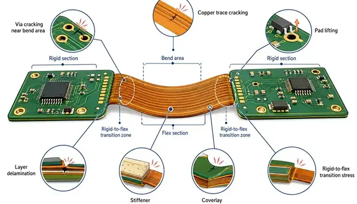
Failures in this zone often manifest as:
- Copper cracking at layer transitions
- Adhesive separation
- Coverlay lifting
IPC-2223 addresses this through the concept of gradual stiffness transition. Instead of abrupt geometry changes, designers are encouraged to implement tapered structures, staggered layer terminations, and filleted edges.
Coverlay and adhesive systems also play a crucial role. Properly designed coverlays act as strain distribution layers, reducing stress at the interface. Adhesives must maintain flexibility while providing sufficient bonding strength across temperature cycles.
A well-designed transition zone behaves less like a boundary and more like a gradient, smoothing out mechanical discontinuities.
5. Common IPC-2223 Violations and Failure Mechanisms (Failure Engineering View)
Understanding failure mechanisms provides deeper insight into why IPC-2223 rules exist. Most violations are not immediately catastrophic—they evolve into failures under repeated stress or environmental exposure.
5.1 Over-tight or Over-relaxed Bend Radius
Designers sometimes underestimate the importance of bend radius, either making it too tight (to save space) or excessively large (assuming safety). Both extremes introduce problems.
When the radius is too small, tensile strain increases sharply, accelerating copper fatigue. The strain relationship shows that reducing radius directly increases strain, leading to early crack initiation.
Conversely, overly relaxed designs may introduce unintended movement, causing unpredictable stress distribution during operation.
5.2 Poor Via Strategy in Flex Areas
Placing vias within flex regions creates a coupled failure mechanism: electrical discontinuity driven by mechanical fatigue. Cracks often initiate at the via barrel or pad interface, eventually leading to intermittent or permanent open circuits.
This is one of the most common causes of latent failures—products pass initial tests but fail in the field.
5.3 Layer Delamination Under Thermal Cycling
Delamination is a progressive failure driven by repeated expansion and contraction. When materials with mismatched CTEs are bonded together without proper compliance, shear stress accumulates at the interface.
Over time, micro-separation grows into visible delamination, often accompanied by electrical instability.
5.4 Incorrect Stiffener Placement
Stiffeners are intended to reduce stress—but when placed incorrectly, they do the opposite. If a stiffener ends abruptly near a bend zone, it creates a new stress concentration point.
Instead of distributing stress, it localizes it, leading to cracking or solder joint failure.
5.5 Improper Coverlay / Mask Design
Coverlays serve as protective and mechanical elements, but poor design can introduce new risks. Inadequate adhesion or incorrect openings allow moisture ingress, leading to:
- Corrosion of copper traces
- Electrical leakage or shorting
- Contamination buildup
Proper coverlay design must balance flexibility, protection, and adhesion reliability.
6. How Engineers Should Actually Design IPC-2223 Compliant Boards
A practical workflow from concept to manufacturable reliability
Designing a rigid-flex circuit that truly complies with IPC-2223 is less about checking rules at the end and more about embedding reliability decisions from the very beginning. The most effective engineering teams follow a structured workflow that integrates mechanical behavior, material science, and manufacturability at every stage.
The process begins with defining how the circuit will move in real use.
Step 1: Define Motion Profile (Static vs Dynamic Flex)
Every rigid-flex design starts with a simple but critical question: Will this circuit move once or repeatedly? Static flex applications—such as folding during assembly—experience limited strain cycles, while dynamic flex applications (e.g., hinges, wearables, printers) may endure thousands or millions of cycles.
This distinction directly determines allowable strain levels and fatigue life. For dynamic applications, copper fatigue becomes the dominant failure mechanism, and conservative design margins must be applied. Engineers often model fatigue life using strain-based relationships derived from material fatigue theory, where higher strain amplitudes sharply reduce lifecycle durability.
Step 2: Define Mechanical Constraints (Bend Radius Envelope)
Once motion is defined, the next step is to establish the allowable bend radius range. This is not a single value, but an envelope that accounts for assembly variation, user handling, and manufacturing tolerances.
Using the strain relationship:
Engineers can determine whether a proposed bend radius keeps strain within acceptable limits. For example, reducing thickness by 20% has the same strain-reduction effect as increasing bend radius by 20%, which creates a powerful trade-off during design optimization.
A practical design table is often used early in development:
| Stack Thickness (mm) | Target Application | Minimum Bend Radius (mm) |
|---|---|---|
| 0.10 | Dynamic flex | ≥ 1.5–2.0 |
| 0.20 | Dynamic flex | ≥ 3.0–4.0 |
| 0.20 | Static flex | ≥ 1.5–2.0 |
This ensures that mechanical constraints are defined before layout begins.
Step 3: Build Stack-up Strategy (Material + Bonding)
Stack-up design translates mechanical requirements into physical structure. Engineers must balance flexibility, strength, and manufacturability by selecting appropriate materials and bonding systems.
Key considerations include:
- Polyimide thickness and modulus
- Copper type (rolled annealed vs electrodeposited)
- Adhesive vs adhesiveless construction
Adhesiveless laminates generally offer improved dimensional stability and reduced delamination risk, particularly under thermal cycling. However, adhesive systems can provide stress absorption if properly matched.
A typical comparison illustrates the trade-offs:
| Stack Type | Advantage | Risk |
|---|---|---|
| Adhesive-based | Better stress absorption | Interface delamination |
| Adhesiveless | Higher reliability, thinner stack | Higher process sensitivity |
| Stack Type | Advantage | Risk |
|---|---|---|
| Adhesive-based | Better stress absorption | Interface delamination |
| Adhesiveless | Higher reliability, thinner stack | Higher process sensitivity |
Stack-up decisions should always align with the defined bend and thermal requirements.
Step 4: Route Flex-Safe Interconnects (Via + Trace Strategy)
Routing in flex regions must follow mechanical logic, not just electrical optimization. Straight traces aligned perpendicular to the bend axis experience maximum strain, while curved or angled traces distribute stress more evenly.
Vias should be excluded from dynamic flex zones whenever possible. If unavoidable, they must be reinforced and positioned outside peak strain areas.
A refined routing strategy typically includes:
| Design Feature | Recommended Practice |
|---|---|
| Trace geometry | Curved or 45° routing |
| Trace orientation | Parallel to bend axis when possible |
| Via placement | Outside dynamic flex regions |
| Pad design | Use teardrop reinforcement |
This approach minimizes stress concentration and extends fatigue life.
The design objective is to maintain flex regions as deformation zones without mechanical load, preserving their long-term durability.
Step 6: Design Transition Architecture
The transition between rigid and flex sections is one of the most critical areas in a rigid-flex design. Failures often originate here due to abrupt changes in stiffness, which create concentrated mechanical stress.
A reliable design treats the transition as a gradual change rather than a sharp boundary. This can be achieved by tapering dielectric layers, staggering copper terminations, and using smooth geometric features instead of sharp edges.
By reducing stiffness discontinuities, the transition region distributes stress more evenly, significantly improving fatigue resistance. In well-designed structures, this area behaves like a gradient rather than a weak interface.
Step 7: Add Reinforcement Features (Stiffeners, Coverlay)
Reinforcement features play a key role in controlling stress and improving structural stability. Stiffeners are typically added under component areas to provide mechanical support and prevent excessive deformation during assembly or operation.
Coverlays, on the other hand, serve both protective and mechanical functions. They shield copper traces from environmental exposure while also helping to distribute strain across the surface of the flex circuit.
The effectiveness of these features depends on proper design. For example, a stiffener that ends too close to a bend region can create a new stress concentration point instead of relieving stress. Similarly, poorly bonded coverlays can lead to moisture ingress or delamination.
A well-integrated reinforcement strategy ensures that stress is managed rather than unintentionally amplified.
Step 8: DFM Review Against IPC-2223 Checklist
Before finalizing the design, a comprehensive Design for Manufacturability (DFM) review is essential. This step ensures that the design can be reliably produced while maintaining compliance with IPC-2223 requirements.
Manufacturers evaluate factors such as layer alignment, material behavior during lamination, drilling and plating feasibility, and adhesion reliability. Even if a design meets theoretical requirements, it must also be robust against real-world production variations.
A successful DFM review reduces the risk of low yield, rework, and long-term reliability issues. It also ensures that the design intent is preserved throughout the manufacturing process.
7. IPC-2223 Design Checklist (High-Value Engineering Control Tool)
A structured checklist provides a final validation step before fabrication. It helps engineers confirm that all critical mechanical and material considerations have been addressed.
| Design Aspect | Verification Requirement |
|---|---|
| Bend radius | Calculated and validated against thickness |
| Flex region vias | Eliminated or relocated |
| Component placement | Restricted to rigid or reinforced areas |
| Transition design | Gradual stiffness change implemented |
| Material compatibility | CTE mismatch evaluated and minimized |
| Coverlay application | Continuous and properly adhered |
| Stiffener placement | Positioned away from bend regions |
| Thermal stress performance | Verified through simulation or calculation |
This checklist reflects the core principle of IPC-2223: preventing mechanical failure through disciplined design control.
8. Advanced Design Insights (What Most Articles Miss)
Dynamic Flex Fatigue Lifecycle
Many design guides focus only on bend radius, but long-term reliability depends on fatigue life under repeated strain. Copper does not fail immediately; instead, it degrades gradually under cyclic loading.
Fatigue behavior follows a nonlinear trend, where small increases in strain can significantly reduce lifecycle performance. This is why dynamic flex designs require conservative strain limits, even if short-term testing appears acceptable.
Signal Integrity in Flex Regions
Flex circuits also present unique signal integrity challenges. When a circuit bends, small geometric changes occur in trace spacing and dielectric thickness, which can affect impedance.
The relationship between impedance and physical structure can be expressed as:
Where:
- L = inductance
- C = capacitance
Even minor variations in these parameters can impact high-speed signal performance. For critical signals, routing through dynamic flex regions should be minimized or carefully simulated.
Mechanical-Electrical Coupling Effects
Rigid-flex circuits inherently couple mechanical and electrical behavior. Mechanical strain can alter conductor resistance, degrade interconnects, or initiate micro-cracks that lead to intermittent electrical faults.
This coupling makes failure analysis more complex, as electrical issues may originate from mechanical causes. A robust design must account for both domains simultaneously.
Manufacturing Tolerances and Real-World Variation
No manufacturing process is perfectly uniform. Variations in material thickness, adhesive flow, and layer alignment can all influence final performance.
These variations can increase localized strain beyond calculated values, especially in tight bends or transition regions. For this reason, IPC-2223 encourages conservative design margins rather than designs that operate at theoretical limits.
A reliable rigid-flex design remains functional not only under ideal conditions, but also under the variability of real-world production.
9. Industry Applications Driving IPC-2223 Adoption
The increasing adoption of rigid-flex circuits across multiple industries is not driven by convenience alone, but by the need to meet strict reliability requirements under complex mechanical and environmental conditions.
IPC-2223 has become a critical framework because it addresses the fundamental reality that these circuits must function as both electrical systems and mechanical structures.
In aerospace applications, rigid-flex circuits operate under continuous vibration, wide temperature ranges, and pressure variations.
These conditions create cyclic mechanical stress combined with thermal expansion effects. The interaction between vibration-induced strain and thermal strain can be approximated as:
εtotal=εmechanical+εthermal
This combined strain significantly accelerates fatigue in copper conductors and interconnects. Aerospace systems, therefore, require conservative design margins, controlled material selection, and strict adherence to IPC-2223 principles to ensure long-term reliability in mission-critical environments.
Medical devices present a different but equally demanding challenge. The trend toward miniaturization, especially in wearable and implantable devices, requires ultra-thin and highly flexible circuits.
These designs often operate in dynamic conditions while maintaining strict reliability standards due to patient safety requirements. Even minor mechanical failures can lead to device malfunction, making fatigue resistance and material stability essential design priorities.
In the automotive sector, rigid-flex circuits are widely used in applications involving repeated motion, such as steering systems, sensors, and camera modules. These systems experience continuous vibration and thermal cycling over long lifetimes.
Automotive qualification standards often require operation across temperature ranges from -40°C to 125°C, which amplifies CTE mismatch effects and increases the risk of delamination and interconnect fatigue.
Consumer electronics push rigid-flex design toward extreme miniaturization and thinness. Foldable devices, compact cameras, and wearable technology rely on flexible interconnects to achieve space efficiency.
However, reducing thickness increases susceptibility to mechanical damage if not properly designed. IPC-2223 provides the framework to balance thinness with durability by controlling strain and material behavior.
A comparison of industry requirements highlights how different stress profiles drive design priorities:
| Industry | Primary Stress Factors | Key Design Focus |
|---|---|---|
| Aerospace | Vibration, thermal extremes | Fatigue resistance, material stability |
| Medical Devices | Miniaturization, reliability | Thin structures, long-term durability |
| Automotive | Repeated motion, thermal cycling | Robust interconnects, CTE control |
| Consumer Electronics | Space constraints, bending | Ultra-thin design, strain control |
Across all these industries, the common requirement is clear: rigid-flex circuits must maintain performance under mechanical stress over time. IPC-2223 enables this by translating physical behavior into practical design constraints.
10. Future of Rigid-Flex Design Standards
Rigid-flex design is evolving beyond static rule-based guidelines toward a more predictive and data-driven approach. As product complexity increases, traditional design methods are no longer sufficient to guarantee reliability.
One of the most significant developments is the adoption of simulation-driven design. Finite Element Analysis (FEA) allows engineers to model stress distribution, deformation, and fatigue behavior before fabrication. When combined with electrical simulation, designers can evaluate both mechanical and signal integrity performance simultaneously.
For example, stress distribution in a bend region can be visualized and optimized by analyzing strain gradients across the stack-up. This reduces reliance on conservative assumptions and enables more efficient designs without compromising reliability.
Another emerging trend is the use of artificial intelligence in Design for Manufacturability validation. AI-driven tools can analyze layout data, identify potential failure points, and recommend design improvements based on large datasets of past designs and failures.
This reduces human error and accelerates design cycles while improving compliance with IPC-2223 requirements.
Material innovation is also shaping the future of rigid-flex circuits. New flexible substrates with lower and more stable coefficients of thermal expansion are being developed to reduce thermal stress.
These materials improve dimensional stability and reduce the risk of delamination, especially in high-temperature or high-reliability applications.
The importance of early-stage compliance is increasing as well. Instead of validating designs after completion, engineers are integrating IPC-2223 principles during concept development. This shift reduces redesign cycles and ensures that mechanical reliability is built into the design from the beginning.
These trends indicate a transition from reactive design validation to proactive reliability engineering, where potential failures are predicted and eliminated before they occur.
11. Conclusion: IPC-2223 as a Reliability Blueprint
IPC-2223 should not be viewed as a simple set of design rules. It is a comprehensive reliability blueprint that integrates mechanical behavior, material science, and manufacturing constraints into a unified framework.
Rigid-flex circuits fail when mechanical realities are ignored. Copper fatigue, material mismatch, and stress concentration are not abstract concepts—they are predictable physical phenomena that directly impact product performance and lifespan. IPC-2223 translates these phenomena into actionable design guidance that prevents failure rather than reacting to it.
True compliance means more than meeting specifications. It requires achieving a balance between performance, manufacturability, and lifecycle reliability. A design that performs well electrically but fails mechanically cannot be considered successful.
The key takeaway is straightforward: successful rigid-flex design depends on respecting the mechanical nature of the system. Electrical function alone is not enough. Engineers who apply IPC-2223 as a design philosophy—not just a checklist—can create products that are not only functional, but durable, manufacturable, and reliable over time.

