
How to Choose a Flex PCB Substrate? A Failure-Driven Selection Guide for Engineers
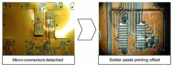

When engineers investigate failed flexible printed circuits, the root cause is often not trace routing, solder joints, or component placement. Instead, the failure frequently originates from an inappropriate substrate choice made during the early design stage.
A flexible PCB substrate serves as the mechanical foundation of the circuit.
It supports copper conductors, provides electrical insulation, and determines how the circuit responds to heat, bending stress, moisture exposure, and chemical attack.
Selecting the wrong material can result in conductor cracking, layer delamination, dimensional instability, signal degradation, or premature product failure.
Many design teams begin by asking which material is most popular—Polyimide (PI), Polyester (PET), or Liquid Crystal Polymer (LCP). However, experienced engineers approach the problem differently.
Rather than starting with material names, they first identify the greatest risk the product will face during its lifecycle.</p>
Will the circuit flex thousands of times? Will it experience solder reflow temperatures above 240°C? Will it operate in a humid industrial environment?
Will signal integrity at gigahertz frequencies be critical? Or is cost the primary concern?
The answers to these questions determine the optimal substrate more effectively than any material datasheet alone.
This article introduces a failure-driven framework that helps engineers select the most suitable flex PCB substrate based on the application’s primary risk factors.
5 Questions to Ask Before Choosing Any Flex PCB Substrate
Before evaluating material properties, engineers should define the operating conditions of the product.
A substrate that performs exceptionally in one environment may become a liability in another.
The first consideration is mechanical stress.
Products such as foldable devices, wearable electronics, medical catheters, and robotic systems may require thousands or even millions of bending cycles throughout their service life.
In these applications, fatigue resistance becomes the dominant selection criterion.
Thermal requirements represent the second major consideration. During assembly, most electronic products undergo lead-free reflow soldering temperatures between 240°C and 260°C.
Substrates with insufficient thermal resistance may shrink, warp, or permanently deform. Signal integrity requirements form the third consideration.
High-speed digital systems, RF modules, radar systems, and 5G communication devices require materials with low dielectric loss and stable electrical characteristics.
Environmental conditions also play a significant role.
Moisture absorption, chemical exposure, and temperature cycling can accelerate material degradation and reduce long-term reliability.
Finally, every project must balance performance against budget constraints.
While high-performance materials offer superior reliability, they may not be economically justified for cost-sensitive products with relatively simple requirements.
The table below summarizes the key questions that should guide substrate selection.
| Design Question | Primary Concern | Recommended Material Direction |
|---|---|---|
| Will the circuit bend repeatedly? | Fatigue resistance | PI |
| Will it experience reflow soldering? | Thermal stability | PI |
| Does it carry high-frequency signals? | Dielectric performance | LCP or PTFE |
| Will it operate in harsh environments? | Moisture and chemical resistance | PI or LCP |
| Is minimizing cost the priority? | Manufacturing economics | PET |
Start with the Biggest Risk
Instead of comparing materials feature by feature, a more practical approach is to identify the greatest threat to product reliability and select the substrate capable of mitigating that risk.
Risk #1: Repeated Bending
Repeated flexing is one of the most demanding conditions a flexible circuit can encounter.
Every bend generates tensile and compressive stresses within the substrate and copper conductors.
Over time, these stresses accumulate and may cause conductor fatigue, substrate cracking, or delamination.
For dynamic-flex applications, Polyimide remains the industry standard.
Its molecular structure provides exceptional flexibility while maintaining dimensional stability under repeated mechanical loading.
Polyimide substrates can withstand thousands or even millions of flex cycles when properly designed.
By contrast, PET performs well in static-flex applications but exhibits significantly lower fatigue resistance under continuous movement.
Although PET offers attractive cost advantages, repeated bending can eventually lead to cracking and mechanical failure.
Typical examples of dynamic-flex applications include foldable smartphones, wearable medical devices, robotics, printer heads, and automotive steering wheel controls.
Flexibility Comparison of Common Flex PCB Substrates
| Material | Dynamic Flex Performance | Typical Applications |
|---|---|---|
| Polyimide (PI) | Excellent | Foldable electronics, wearables |
| PEN | Good | Medium-flex consumer products |
| PET | Limited | Static-flex circuits, LED strips |
| LCP | Good | RF flexible circuits |
For designs involving continuous motion, selecting a lower-cost substrate often results in higher lifecycle costs due to reduced durability and increased field failures.
Risk #2: High Temperature
Temperature resistance becomes critical during both manufacturing and operation.
Lead-free soldering processes typically expose flexible circuits to peak temperatures between 245°C and 260°C.
Materials incapable of tolerating these temperatures may shrink, warp, or lose dimensional accuracy.
Polyimide is widely used because it maintains mechanical integrity at temperatures exceeding 250°C and can survive multiple reflow cycles.
This capability explains its widespread adoption in automotive electronics, aerospace systems, industrial controls, and medical devices.
PET, on the other hand, generally exhibits thermal limitations around 150°C.
While suitable for low-temperature applications, PET may deform during standard SMT assembly processes.
Thermal Performance Comparison
| Material | Maximum Continuous Temperature | Reflow Compatibility |
|---|---|---|
| PI | 200–260°C+ | Excellent |
| PEN | 150–180°C | Limited |
| PET | 120–150°C | Poor |
| LCP | 200–240°C | Excellent |
When thermal exposure is expected, substrate selection should prioritize long-term dimensional stability rather than initial material cost.
Risk #3: RF and High-Speed Signal Integrity
As operating frequencies increase, electrical performance becomes increasingly dependent on substrate properties.
High-frequency signals are affected by dielectric constant (Dk) and dissipation factor (Df).
Materials with lower dielectric loss allow signals to propagate with less attenuation, improving transmission efficiency and reducing noise.
For RF and microwave applications, LCP and PTFE are often preferred because of their exceptionally low dielectric loss characteristics.
These materials maintain stable electrical properties across a broad frequency range, making them suitable for antennas, radar systems, satellite communications, and 5G infrastructure.
Polyimide remains suitable for many digital applications but generally exhibits higher dielectric loss than specialized RF materials.
Electrical Performance Comparison
| Material | Dielectric Constant (Dk) | RF Performance |
|---|---|---|
| PTFE | ~2.1 | Excellent |
| LCP | ~2.9–3.1 | Excellent |
| PI | ~3.2–3.5 | Good |
| PET | ~3.2–3.4 | Moderate |
For frequencies above several gigahertz, choosing the wrong substrate can significantly increase insertion loss and compromise signal quality.
Risk #4: Moisture and Chemical Exposure
Environmental durability often determines long-term product reliability.
Industrial equipment, automotive systems, outdoor electronics, and medical devices frequently encounter humidity, cleaning chemicals, oils, and temperature cycling.
These environmental factors can alter electrical properties, accelerate aging, and weaken interlayer bonds.
Polyimide provides excellent chemical resistance and maintains performance in many harsh operating conditions.
However, it can absorb some moisture, which designers must consider in highly sensitive applications.
LCP offers a significant advantage due to its extremely low moisture absorption characteristics.
This property helps maintain dimensional stability and electrical performance even in humid environments.
Environmental Resistance Comparison
| Material | Moisture Resistance | Chemical Resistance |
|---|---|---|
| LCP | Excellent | Excellent |
| PI | Very Good | Excellent |
| PEN | Good | Good |
| PET | Moderate | Moderate |
For electronics exposed to challenging environments, environmental resistance should be considered as carefully as thermal or electrical performance.
Risk #5: Budget Pressure
Not every flexible circuit is destined for an aircraft, surgical instrument, or autonomous vehicle.
Many products operate under relatively mild conditions where manufacturing cost becomes the dominant design constraint.
In such cases, selecting the most expensive substrate may provide little practical benefit while significantly increasing production expenses.
Polyester (PET) is often the preferred choice for cost-sensitive flexible circuits.
Compared with polyimide, PET offers lower material and processing costs, making it attractive for high-volume consumer products.
Although PET lacks the thermal resistance and dynamic-flex durability of premium materials, it performs adequately in applications where the circuit experiences limited movement and moderate operating temperatures.
Common examples include LED lighting strips, membrane switches, disposable medical sensors, RFID tags, and consumer electronic accessories.
In these products, the circuit typically remains stationary after installation, reducing the need for extreme flexibility or thermal endurance.
The key challenge for designers is distinguishing between “low-cost” and “over-specified.”
A substrate should provide sufficient performance for the intended application without introducing unnecessary material costs.
Typical Cost Comparison of Flex PCB Substrates
| Material | Relative Material Cost | Typical Applications |
|---|---|---|
| PET | Low | LED strips, sensors, consumer products |
| PEN | Medium | Displays, wearable electronics |
| PI | High | Automotive, aerospace, medical |
| LCP | Very High | RF, microwave, 5G systems |
| PTFE | Very High | High-frequency communication systems |
Although PET generally offers the lowest upfront cost, selecting it for applications requiring repeated bending or high-temperature soldering can lead to premature failures and higher total ownership costs.
Therefore, engineers should evaluate lifecycle cost rather than material price alone.
Flex PCB Substrate Decision Matrix
After evaluating the major risk factors, engineers can simplify substrate selection using a practical decision matrix.
Rather than comparing dozens of material properties simultaneously, the matrix focuses on matching the primary application requirement with the substrate best suited to address it.
Flex PCB Substrate Selection Matrix
| Primary Requirement | Recommended Material | Selection Rationale |
|---|---|---|
| Repeated bending | PI | Superior fatigue resistance and bend life |
| High-temperature assembly | PI | Excellent thermal stability during reflow |
| 5G and RF circuits | LCP / PTFE | Low dielectric loss and stable signal transmission |
| Moisture-sensitive environments | PI / LCP | Strong environmental resistance |
| Lowest manufacturing cost | PET | Economical for static-flex applications |
| Balanced performance and cost | PEN | Compromise between PET and PI |
The matrix should be viewed as a starting point rather than a universal rule.
In many advanced designs, engineers must balance multiple requirements simultaneously.
For example, a wearable medical device may require both flexibility and moisture resistance, while a 5G antenna module may demand excellent RF performance alongside dimensional stability.
PI vs PEN vs PET — Which One Should You Actually Buy?
Among all flexible substrate materials, Polyimide (PI), Polyethylene Naphthalate (PEN), and Polyester (PET) account for the majority of commercial flex PCB production.
While specialty materials such as LCP and PTFE dominate niche high-frequency applications, most engineers ultimately choose between these three options.
Understanding their strengths and limitations can significantly simplify the selection process.
Polyimide (PI)
Polyimide has long been considered the industry benchmark for flexible circuits. It offers exceptional thermal stability, excellent mechanical flexibility, strong chemical resistance, and proven reliability in demanding environments.
Many automotive control systems, aerospace electronics, industrial sensors, and medical devices rely on PI because it can tolerate both harsh operating conditions and repeated mechanical stress.
Its primary disadvantage is cost. PI substrates typically cost substantially more than PET and moderately more than PEN.
However, for mission-critical applications, the performance benefits often justify the investment.
Typical Characteristics of Polyimide
| Property | Typical Value |
|---|---|
| Maximum operating temperature | Up to 260°C+ |
| Flexibility | Excellent |
| Chemical resistance | Excellent |
| Reliability | Excellent |
| Relative cost | High |
For applications where failure is unacceptable, PI remains the safest choice.
PEN
Polyethylene Naphthalate occupies the middle ground between PET and PI. It offers better thermal resistance, dimensional stability, and environmental performance than PET while maintaining a lower cost than PI.
As electronic devices continue to shrink, PEN has gained popularity in display technologies, wearable electronics, and medium-performance flexible circuits.
However, PEN still falls short of PI in dynamic-flex durability and high-temperature performance. It should be viewed as a compromise material rather than a direct replacement for Polyimide.
Typical Characteristics of PEN
| Property | Typical Value |
|---|---|
| Maximum operating temperature | ~180°C |
| Flexibility | Good |
| Dimensional stability | Good |
| Reliability | Good |
| Relative cost | Medium |
For projects requiring balanced performance and cost control, PEN often provides an attractive solution.
PET
PET remains one of the most widely used flexible circuit substrates due to its affordability and ease of processing.
Its low cost makes it highly attractive for high-volume manufacturing. In applications involving limited thermal exposure and minimal flexing, PET can deliver satisfactory performance at a fraction of the cost of Polyimide.
The tradeoff is reduced heat resistance and shorter fatigue life.
PET is generally unsuitable for repeated flexing or lead-free reflow soldering environments.
Typical Characteristics of PET
| Property | Typical Value |
|---|---|
| Maximum operating temperature | ~150°C |
| Flexibility | Moderate |
| Dynamic flex performance | Limited |
| Reliability | Moderate |
| Relative cost | Low |
When the primary objective is minimizing manufacturing cost, PET often becomes the preferred choice.
Quick Comparison: PI vs PEN vs PET
| Property | PI | PEN | PET |
|---|---|---|---|
| Thermal Resistance | Excellent | Good | Moderate |
| Flexibility | Excellent | Good | Moderate |
| Dynamic Bend Life | Excellent | Moderate | Limited |
| Chemical Resistance | Excellent | Good | Moderate |
| Cost | High | Medium | Low |
| Recommended Applications | Automotive, Medical, Aerospace | Wearables, Displays | LED Strips, Sensors |
Real-World Case Studies
Material selection becomes easier when viewed through practical engineering scenarios.
The following examples demonstrate how experienced designers match substrates to application requirements.
Case Study 1: Foldable Consumer Device
A consumer electronics manufacturer developed a foldable smart device expected to survive more than 100,000 folding cycles during its lifetime.
The primary design challenge was mechanical fatigue.
Every fold generated stress within both the copper conductors and substrate layers. A failure would immediately affect user experience and product reliability.
After evaluating multiple materials, the engineering team selected Polyimide.
The decision was based on PI’s exceptional fatigue resistance, thermal stability, and proven performance in dynamic-flex applications.
Although PET offered significant cost savings, its limited bend life created unacceptable reliability risks.
Design Requirements
| Requirement | Value |
|---|---|
| Flex cycles | >100,000 |
| Operating temperature | Consumer electronics range |
| Reliability target | High |
| Selected substrate | PI |
In this scenario, long-term durability outweighed material cost.
Case Study 2: Low-Cost LED Strip
An LED lighting manufacturer required a flexible circuit for decorative lighting installations.
Unlike foldable devices, the circuit would only be bent once during installation and then remain stationary throughout its service life.
The primary objective was minimizing manufacturing cost while maintaining acceptable electrical performance.
PET emerged as the optimal solution.
The material provided adequate flexibility during installation and reduced substrate costs significantly compared with Polyimide.
Design Requirements
| Requirement | Value |
|---|---|
| Dynamic bending | Minimal |
| Operating temperature | Low |
| Production volume | High |
| Cost sensitivity | High |
| Selected substrate | PET |
This example demonstrates that premium materials are not always necessary.
Case Study 3: 5G Antenna Module
A telecommunications company developed a compact 5G antenna system operating at high frequencies where signal loss directly affected transmission efficiency.
In this application, electrical performance became the dominant concern.
Even small increases in dielectric loss could reduce signal quality and system efficiency.
The engineering team selected LCP because of its low dielectric constant, extremely low moisture absorption, and excellent high-frequency performance.
Although the material cost exceeded that of PI and PET, improved signal integrity justified the investment.
Design Requirements
| Requirement | Value |
|---|---|
| Operating frequency | Multi-GHz |
| Signal loss tolerance | Very low |
| Environmental stability | Critical |
| Selected substrate | LCP |
For RF and microwave applications, electrical performance often outweighs material cost considerations.
7 Costly Mistakes Engineers Make When Choosing a Flex PCB Substrate
Selecting a flex PCB substrate may appear straightforward, but many product failures can be traced back to assumptions made during this stage of development.
Engineers often focus on electrical design while underestimating how substrate characteristics influence long-term reliability.
The following mistakes repeatedly appear in failure analyses across consumer electronics, industrial equipment, automotive systems, and communication products.
Mistake #1: Choosing PET for Dynamic Bending Applications
One of the most common errors is selecting PET solely because of its lower cost.
PET performs well in static-flex applications where the circuit is bent once during installation and remains stationary afterward.
However, repeated bending creates cyclic mechanical stress that can eventually cause conductor fatigue, substrate cracking, or interlayer separation.
Applications such as foldable devices, robotics, wearable electronics, and printer heads typically require Polyimide due to its superior fatigue resistance.
Dynamic Flex Suitability
| Material | Dynamic Flex Capability |
|---|---|
| PI | Excellent |
| PEN | Good |
| PET | Limited |
A substrate that saves a few cents per unit can become extremely expensive when field failures begin to appear.
Mistake #2: Ignoring Soldering Temperature Requirements
Many flexible circuits undergo lead-free SMT assembly, where peak reflow temperatures commonly reach 245–260°C.
If the substrate lacks sufficient thermal stability, dimensional changes may occur during manufacturing.
Warpage, shrinkage, registration issues, and delamination can result from excessive heat exposure.
Design teams sometimes evaluate only operating temperature while overlooking assembly temperature.
Typical Thermal Limits
| Material | Maximum Recommended Temperature |
|---|---|
| PI | 250°C+ |
| LCP | 240°C+ |
| PEN | 180°C |
| PET | 150°C |
A material that survives product operation may still fail during manufacturing.
Mistake #3: Using Standard PI for RF Applications Without Checking Dielectric Loss
Polyimide is often considered the default substrate for flexible circuits.
While it performs exceptionally well in mechanical and thermal applications, it is not always the optimal choice for high-frequency designs.
As frequencies enter the multi-gigahertz range, dielectric loss becomes increasingly important.
Materials such as LCP and PTFE typically provide lower insertion loss and more stable signal transmission than conventional PI.
For 5G antennas, radar modules, satellite communication systems, and millimeter-wave devices, selecting the substrate based solely on flexibility can lead to degraded RF performance.
Typical Electrical Performance
| Material | Dielectric Constant (Dk) | Dissipation Factor (Df) |
|---|---|---|
| PTFE | ~2.1 | Very Low |
| LCP | ~2.9–3.1 | Very Low |
| PI | ~3.2–3.5 | Moderate |
| PET | ~3.2–3.4 | Moderate |
When signal loss directly affects system performance, electrical properties should take priority over familiarity.
Mistake #4: Overlooking Moisture Absorption
Environmental exposure can significantly influence substrate behavior over time.
Moisture absorption may alter dielectric properties, increase dimensional changes, and reduce long-term reliability.
This issue becomes particularly important in outdoor equipment, industrial control systems, automotive electronics, and telecommunications infrastructure.
While Polyimide offers excellent overall performance, it absorbs more moisture than LCP.
For applications requiring extremely stable electrical performance under varying humidity conditions, LCP often provides a measurable advantage.
Moisture Absorption Comparison
| Material | Typical Moisture Absorption |
|---|---|
| LCP | <0.05% |
| PTFE | <0.05% |
| PI | 1–3% |
| PET | 0.2–0.8% |
Ignoring environmental factors can result in reliability problems that may not appear until months or years after deployment.
Mistake #5: Over-Specifying Expensive Materials
Engineers naturally prefer designing with the most capable materials available. However, selecting a premium substrate when the application does not require it can unnecessarily increase product cost.
For example, using aerospace-grade Polyimide in a disposable sensor or LED strip rarely provides meaningful value. In such cases, PET may satisfy all technical requirements while significantly reducing manufacturing expenses.
The goal of material selection is not to identify the highest-performing substrate but to identify the most appropriate substrate.
A successful design balances reliability, manufacturability, and cost.
Mistake #6: Ignoring Bend Radius Requirements
The lifespan of a flexible circuit depends not only on material selection but also on mechanical design.
Even a high-quality Polyimide substrate can fail if subjected to an excessively tight bend radius.
Excessive strain may cause copper cracking, conductor fatigue, and dielectric damage.
According to industry design practices, the minimum bend radius should generally increase as circuit thickness increases.
Typical Design Guidelines
| Application Type | Recommended Minimum Bend Radius |
|---|---|
| Static Flex | 6–10 × Circuit Thickness |
| Dynamic Flex | 10–20 × Circuit Thickness |
Substrate selection and mechanical design should always be evaluated together.
Mistake #7: Selecting a Material Before Consulting the Manufacturer
Many design teams finalize material specifications before discussing manufacturing capabilities with their PCB supplier.
This approach can create unexpected challenges involving material availability, processing limitations, lead times, or production yield.
Certain specialty materials may require specific fabrication processes or longer procurement cycles.
Others may increase manufacturing complexity without providing proportional benefits.
Early collaboration between designers and manufacturers often prevents costly redesigns later in the project.
A substrate that performs perfectly in theory must also be practical to manufacture at scale.
A 60-Second Flex PCB Substrate Selection Flowchart
Although substrate selection can involve dozens of technical parameters, most projects can be narrowed down quickly by focusing on the application’s primary requirement.
The following simplified workflow provides a practical starting point for early-stage design decisions.
- Flex
PCB Material Selection Flowchart
| Design Requirement | Recommended Material |
|---|---|
| Requires repeated bending? | PI |
| Requires operation at RF or microwave frequencies? | LCP or PTFE |
| Requires the lowest possible manufacturing cost? | PET |
| Requires balanced cost and performance? | PEN |
| Requires maximum reliability in harsh environments? | PI |
| Requires minimal signal loss at multi-GHz frequencies? | LCP |
For many engineers, this decision process eliminates unsuitable options within minutes and significantly shortens material evaluation time.
Final Recommendation
Choosing a flex PCB substrate is ultimately an exercise in risk management.
No single material is ideal for every application.
Polyimide offers exceptional durability and thermal stability, but it may be unnecessarily expensive for simple products. PET provides outstanding cost efficiency, yet its limitations become apparent in demanding environments.
PEN fills the gap between performance and affordability, while LCP and PTFE dominate applications where high-frequency electrical performance is critical.
The most successful designs begin by identifying the product’s greatest reliability challenge.
Once the primary failure risk is understood, flex PCB substrate selection becomes much more straightforward.
Whether the concern is repeated bending, thermal exposure, RF performance, moisture resistance, or manufacturing cost, the optimal material is the one that minimizes the risk most likely to cause product failure.
Don’t choose a flex PCB substrate because it is popular. Choose it based on the failure mode your product cannot afford.





