Rigid-Flex PCB Structures and Process Flow: Common Configurations and
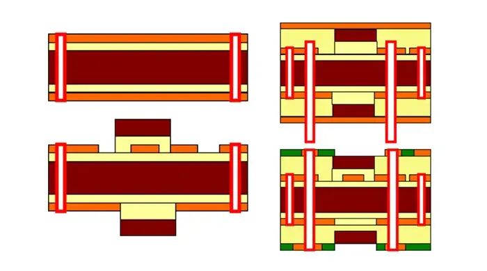
Rigid-Flex PCB Structures and Process Flow: Common Configurations and
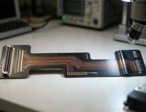
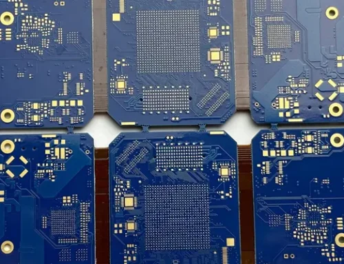
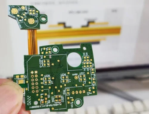
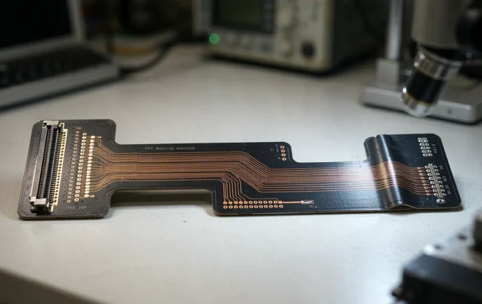
Rigid-flex PCB (R-FPCB, R-FPCB) is a composite printed circuit board formed by combining a flexible PCB with a rigid printed circuit board (PCB) through processes such as lamination, in accordance with relevant manufacturing requirements.
It is suitable for both flexible and rigid areas, offering significant advantages in saving internal product space and reducing the overall size of the finished product.
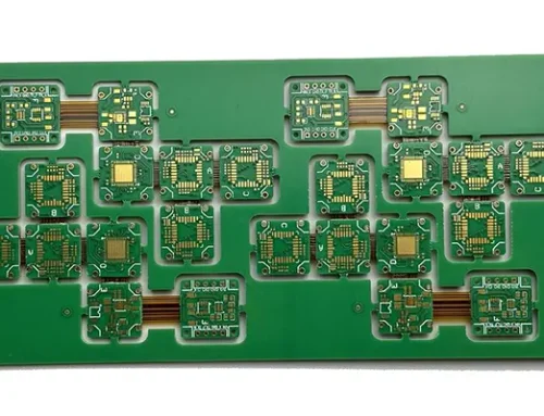
Rigid-flex boards are widely used in products with special design and performance requirements. Manufacturers create rigid-flex boards by bonding one or more rigid layers to a flexible substrate.
Manufacturers establish electrical interconnections between the circuits on the rigid layers and the flexible layer through drilling, through-hole plating, and lamination processes.
Depending on design requirements, this approach optimizes the design for component installation, debugging, and soldering operations, ensuring greater flexibility in the assembly process.
Advantages and Disadvantages of Rigid-Flex Boards
Advantages: Rigid-flex boards combine the characteristics of both FPCs and PCBs. As a result, they can be used in products with special requirements, featuring both flexible and rigid areas.
This is highly beneficial for saving internal space, reducing the size of the finished product, and improving product performance.
Disadvantages: Rigid-flex boards involve a complex manufacturing process that is difficult to execute, resulting in a low yield rate.
They require significant material and labor inputs, making them relatively expensive and extending the production cycle.
There are two common configurations for rigid-flex boards:
1) A combination of one flexible board and several rigid boards (Type 1 board)
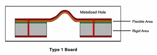
Fig 1
2) A combination of several flexible plates and several rigid plates (Type 2 plate)
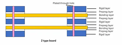
Fig 2
The derived structure is as follows:
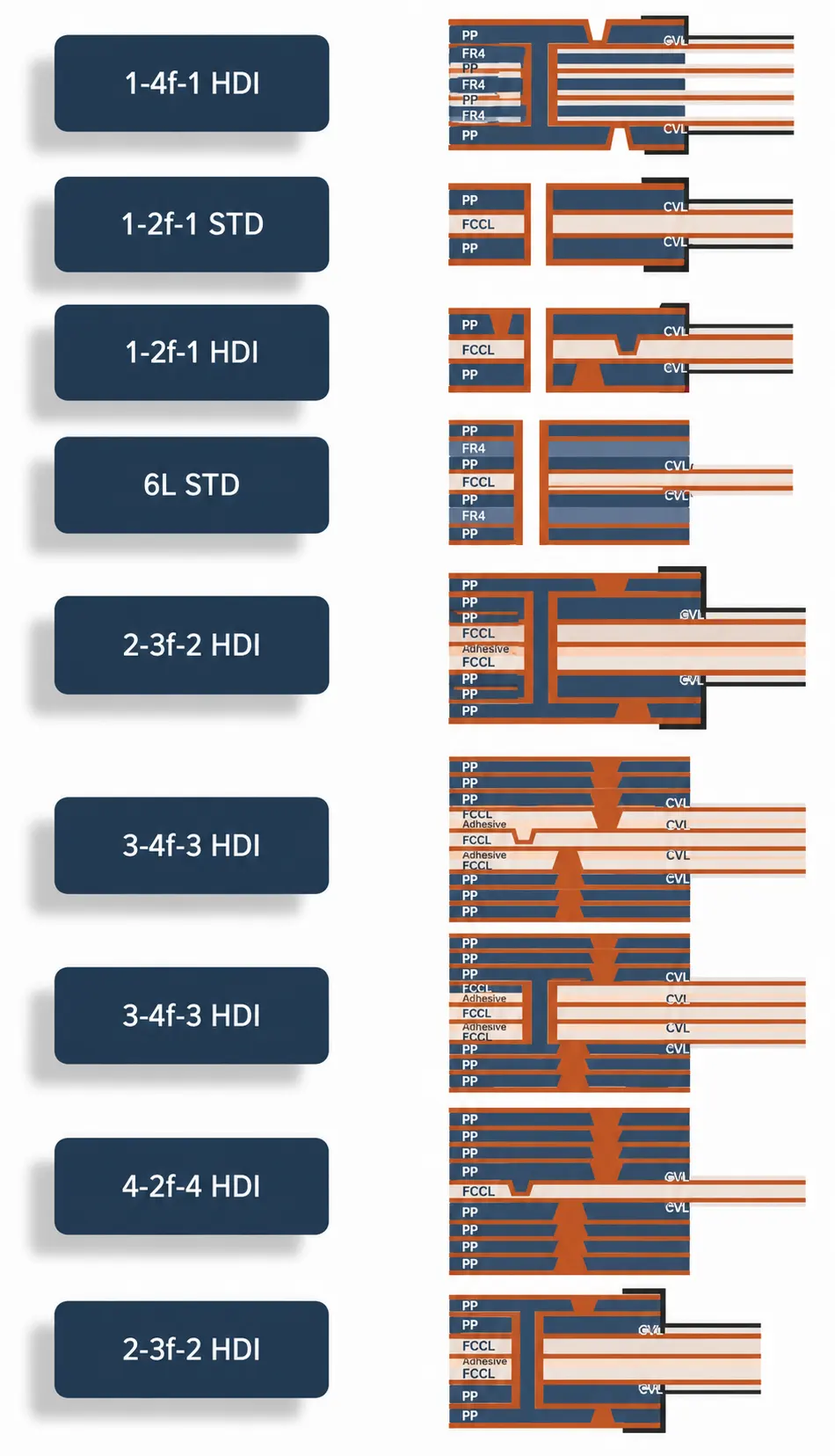
Fig 3
Process Flow
Simplified Process for Single-Sided/Double-Sided Flexible PCB
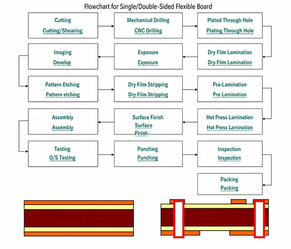
Fig 4
Simplified Process for Multilayer Flexible PCB
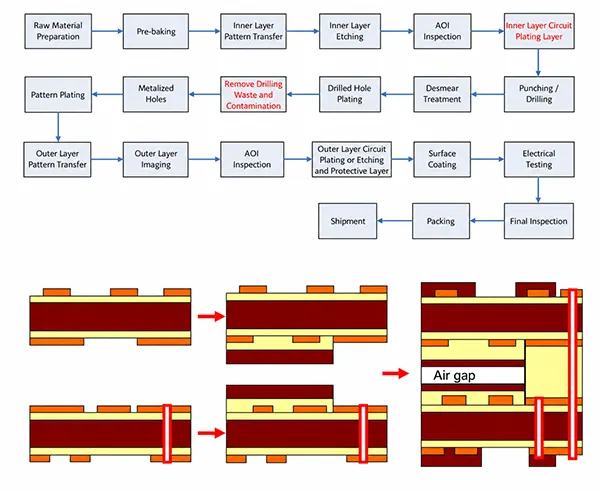
Fig 5
There are various configurations for four-layer flexible circuits: 2+2, 1+2+1, and 1+1+1+1;
Five-layer and six-layer flexible circuit configurations can also be arranged in various combinations using the methods described above.
Process flow of rigid-flex PCB 1
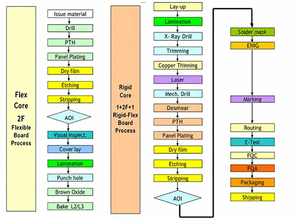
Fig 6
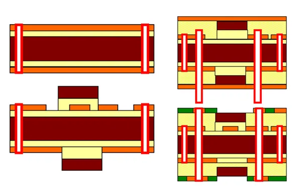
Fig 6.1
Process flow of rigid-flex PCB 2
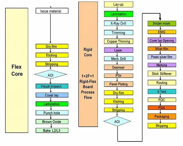
Fig 7
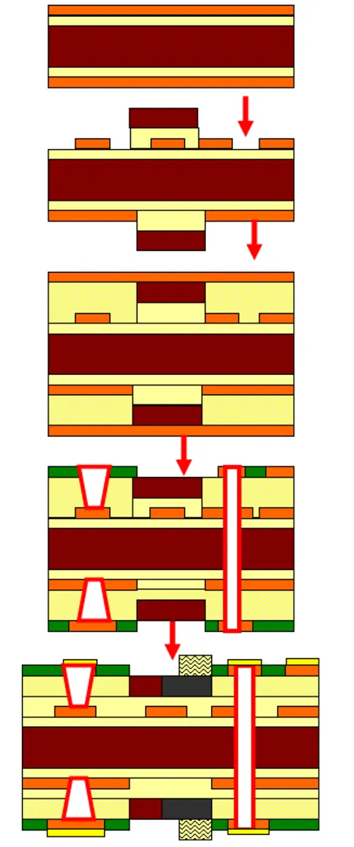
Fig 7.1
Process flow of rigid-flex PCB 3
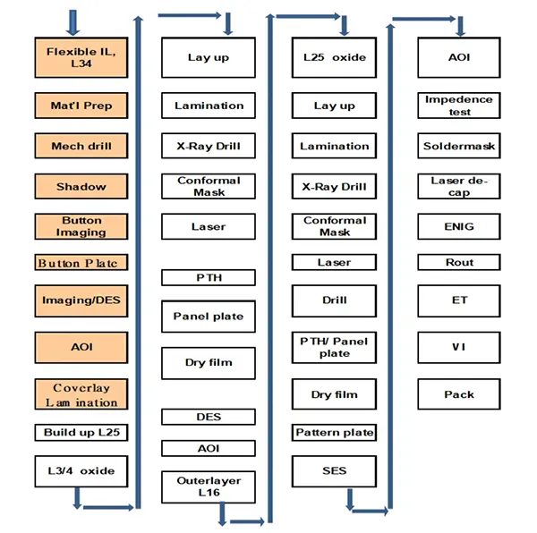
Fig 8
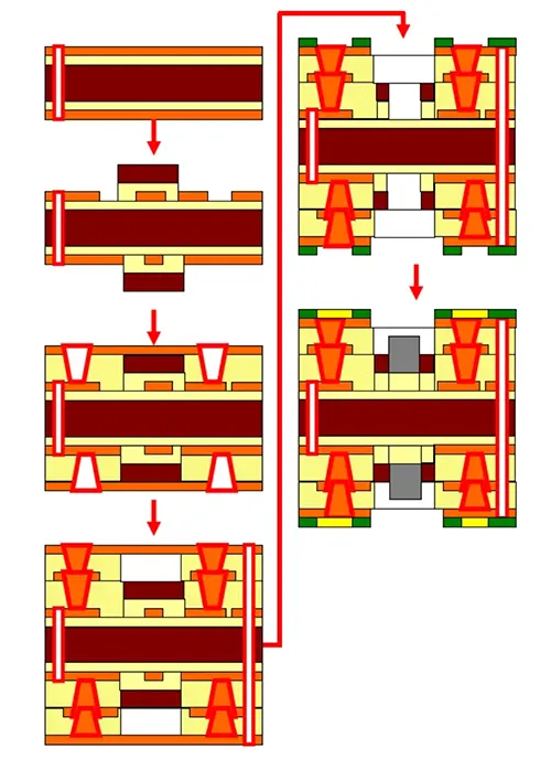
Fig 9
Conclusion
A Rigid-Flex PCB combines the structural strength of rigid PCBs with the flexibility of flexible circuits, making it an ideal solution for compact, high-performance electronic products.
By integrating rigid and flexible sections into a single board, it reduces assembly complexity, saves valuable internal space, and enhances overall system reliability.
Although rigid-flex boards require more sophisticated manufacturing processes, higher material costs, and longer production times than conventional PCBs, their performance and design advantages often outweigh these challenges in demanding applications.
Understanding their structures, configurations, and manufacturing processes enables engineers to select the most suitable rigid-flex solution for modern electronic designs.