Flexible PCBs: Structure, Materials, and Selection Guide
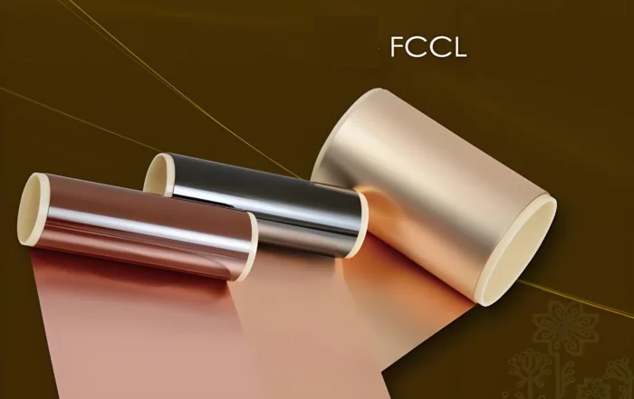
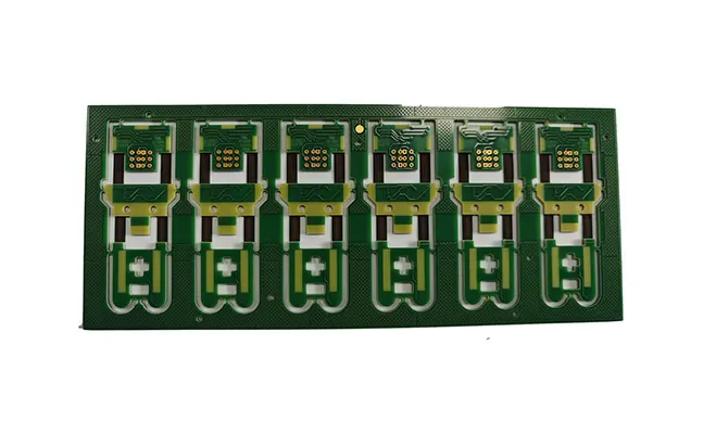
Flexible PCBs allow engineers to bend, roll, and fold circuits freely. Manufacturers use polyimide film as the substrate to produce these circuits, which the industry also calls “soft boards” or “FPCs.”
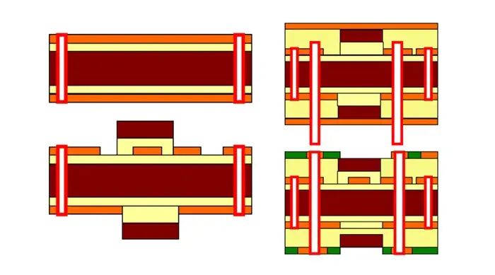
Manufacturers categorize flexible printed circuit manufacturing processes into double-sided flexible printed circuit processes and multilayer flexible printed circuit processes based on the number of layers.
FPCs can withstand millions of dynamic bends without damaging the conductors.
They allow engineers to arrange components according to spatial layout requirements and move or extend them freely in three-dimensional space. This design capability integrates component assembly with conductor connections.
Flexible printed circuits can significantly reduce the size and weight of electronic products, meeting the industry’s demand for higher density, miniaturization, and greater reliability.
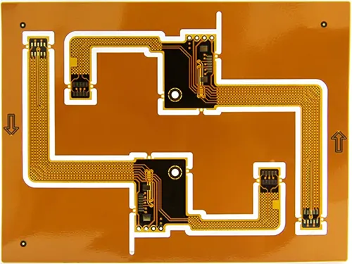
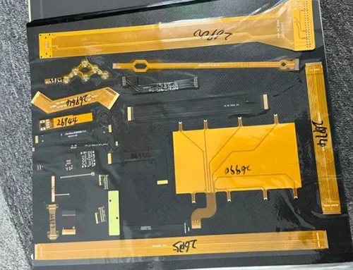
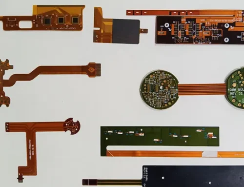
Fig 1 Flexible PCBs
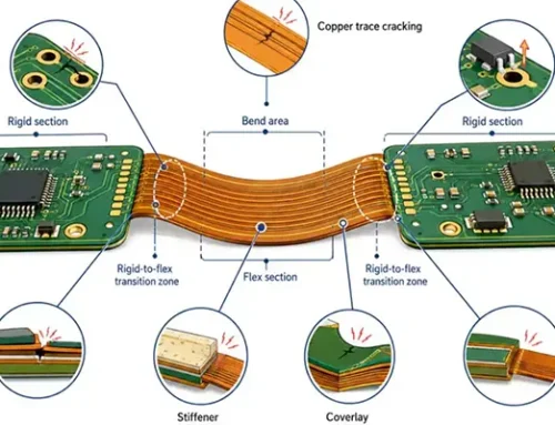
Structure of Flexible Circuit Boards: Based on the number of layers of conductive copper foil, they are classified into single-layer boards, double-layer boards, multilayer boards, double-sided boards, and so on.
Material Properties and Selection Methods
Base Material
The material is polyimide (POLYMIDE), a high-temperature-resistant, high-strength polymer.
It can withstand temperatures of 400 degrees Celsius for 10 seconds and has a tensile strength of 15,000–30,000 PSI.
The 25-micrometer-thick substrate is the most affordable and the most widely used.
Manufacturers should select a 50-micrometer substrate when a stiffer circuit board is required. Conversely, they should choose a 13-micrometer substrate when a more flexible circuit board is needed.
Substrate Adhesive
There are two types: epoxy resin and polyethylene, both of which are thermosetting adhesives.
Polyethylene has relatively low strength; choose it if you want the PCB to be more flexible.
The thicker the substrate and the adhesive layer, the stiffer the PCB will be.
Manufacturers should use thinner substrates and adhesive layers in areas that experience significant bending.
This approach minimizes stress on the copper foil surface and reduces the risk of microcracks forming in the copper foil.
In these sections, designers should choose single-layer boards whenever possible.
Copper Foil
There are two types: rolled copper and electrolytic copper. Rolled copper has high strength and is resistant to bending, but it is more expensive.
Electrolytic copper offers a much lower cost, but it provides lower strength and tends to break more easily.
Manufacturers generally use it in applications that require minimal bending.
The choice of copper foil thickness depends on the minimum trace width and minimum spacing.
The thinner the copper foil, the smaller the minimum width and spacing that can be achieved. When selecting rolled copper, pay attention to the rolling direction of the copper foil.
The rolling direction of the copper foil must align with the PCB’s primary bending direction.
Protective Film and Clear Adhesive
A 25-μm protective film makes the PCB relatively stiff but is relatively inexpensive.
For PCBs that undergo significant bending, it is best to use a 13-μm protective film.
Transparent adhesive is also available in two types: epoxy resin and polyethylene.
PCBs using epoxy resin are stiffer. After hot pressing is complete, some transparent adhesive will be squeezed out from the edges of the protective film.
If the pad dimensions exceed the size of the openings in the protective film, this extruded adhesive will reduce the pad size and cause irregular edges.
In this case, a 13 μm-thick transparent adhesive should be selected whenever possible.
Pad Plating
For PCBs with significant bending and partially exposed pads, electroplated nickel plus electroless gold plating should be used.
The nickel layer should be as thin as possible: 0.5–2 μm, and the electroless gold layer should be 0.05–0.1 μm.
Conclusion
Flexible PCBs have become essential components in modern electronic products due to their excellent flexibility, lightweight structure, and high reliability.
By using polyimide substrates and carefully selecting materials such as adhesives, copper foil, protective films, and pad plating, FPCs can achieve the required balance between flexibility, durability, and electrical performance.
The proper selection of substrate thickness, copper foil type, and protective materials is critical for ensuring long-term reliability, especially in applications involving repeated bending or complex three-dimensional assembly.
As electronic devices continue to demand higher density, smaller sizes, and greater design flexibility, FPC technology will continue to play an important role in industries such as consumer electronics, automotive electronics, medical devices, and intelligent equipment.