Rigid-Flex PCB Drilling: New Technologies to Reduce Burrs and Improve Yield
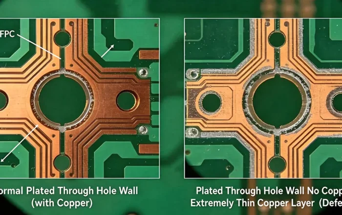
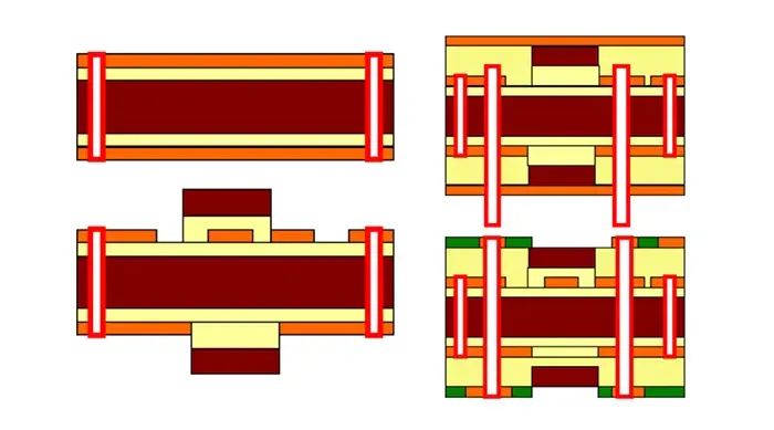
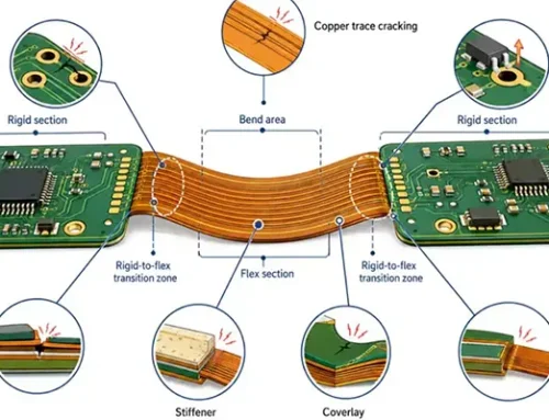
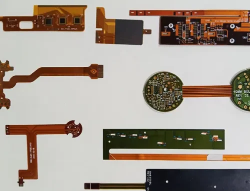
Rigid-Flex Printed Circuit Boards (R-FPCBs) are composite printed circuit boards formed by combining flexible printed circuit boards (FPCBs) and rigid printed circuit boards (PCBs) through processes such as lamination, in accordance with relevant manufacturing requirements.
It is suitable for both specific flexible areas and specific rigid areas, offering significant advantages in saving internal product space and reducing the volume of the finished product, and is widely used in products with special requirements.
Due to the unique nature of the product’s structural design, the thickness of the flexible regions is typically thinner than that of the rigid regions, resulting in a height difference in the rigid-flex boards.
The thinner areas form recessed zones; during drilling, a gap exists between the backing plate and the flexible region (recessed zone), leading to significant burrs from mechanical drilling.
Additionally, customers may encounter flatness issues during component soldering, increasing the risk of component detachment.
This study will explore the challenges associated with the mechanical drilling of R-FPCBs.
Analysis of the Causes of Burrs in Mechanical Drilling of Rigid-Flex PCBs
Due to the height difference between the flexible and rigid regions of R-FPCBs, the use of cushioning materials during lamination tends to increase material compression, resulting in an uneven board surface;
Subsequently, during mechanical drilling of through-holes, a gap exists between the spacer and the board being processed, which easily causes burrs at the hole openings upon drill exit (see Figure 1).
Typically, PCB manufacturers set appropriate drilling parameters and drill bit life expectations based on different materials or select suitable spacers to reduce burrs;
However, when the height difference on the PCB surface is significant, the methods mentioned above struggle to eliminate the gap between the PCB and the spacer, resulting in poor burr suppression (burrs > 30 μm).
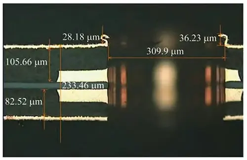
Figure 1. The difference in elevation results in large burrs
Common Methods for Reducing Drilling Burrs in Rigid-Flex Boards
(1) Grinding:
After drilling, use an automated grinding line to smooth out the burrs.
(2) Adding lamination aids:
During the drilling process, use riveted aluminum sheets or laminate epoxy boards with riveted aluminum sheets (see Figure 2) to ensure the epoxy boards and aluminum sheets are tightly bonded to the board surface.
At the same time, the epoxy boards and aluminum sheets provide structural support to reduce drilling burrs and limit them to 10–20 μm.
(3) Dry film lamination process:
Before mechanical drilling, a dry film is laminated onto both the top and bottom surfaces of the board;
The dry film in the areas to be drilled is exposed, and then the unexposed portions are removed through a development process, leaving only the exposed dry film;
The dry film serves as a substitute for covers and shims to provide structural support, thereby reducing drilling burrs and limiting them to 2–6 μm.
New Drilling Technologies for Rigid-Flex Boards
New Technology 1 (Full-Surface Washable Coating Method)
This technology involves first applying a layer of washable coating to the board surface (see Figures 3 and 4); after screen printing and UV curing, the coating bonds seamlessly to the board surface.
This coating possesses extremely high hardness and can serve as a substitute for a backing plate during the drilling process, thereby reducing drilling burrs;
After drilling is complete, the coating is removed by washing with heated tap water, causing no damage to the board.
New Technology 2 (Partial Application of Washable Coating Method)
This technology involves applying a layer of coating to specific areas on the substrate to fill surface irregularities, thereby mitigating the issue of drilling burrs caused by these irregularities. The specific procedure is as follows.
(1) Obtain information on the recessed areas of the rigid-flex board:
This includes the number, location, dimensions, and depth of the recessed areas on the board; this information can be obtained from design documentation.
Ensure that the area of each printing zone is no smaller than the drilling area and no larger than the corresponding recessed area.
(2) Determine printing parameters and perform printing:
Based on the information about the recessed areas, define the printing areas and coating thickness on the substrate; use screen printing to precisely apply the coating to the designated printing areas.
(3) Cure the coating:
Cure the coating; the substrate with the coating applied to specific areas is shown in Figure 5.
(4) Drilling:
Use the raised coating to fill the recessed areas of the rigid-flex board; during the drilling operation, ensure there are no gaps between the coating and the recessed areas to reduce drilling burrs, as shown in Figure 6.
Comparison of Conventional Methods and New Technologies
Table 1 presents a comparative analysis of conventional methods for reducing burrs in rigid-flex PCB drilling and new technologies.
As shown in Figure 7, there is a gap at the step, and Figure 8 illustrates defects in the inner-layer interconnects.
| Item | Brushing | Press-Fit Auxiliary Material | Adhesive Film | New Technology 1 | New Technology 2 |
|---|---|---|---|---|---|
| Drilling method | Brushing | Press-fit auxiliary material | Adhesive film | New technology 1 | New technology 2 |
| Bristle / μm | 30–70 | 10–20 | 2–6 | 1–5 | 1–5 |
| Maximum drill stack height | 1 sheet/stack | 1 sheet/stack | 2 sheets/stack | 2 sheets/stack | 1 sheet/stack |
| Processing time / min | 70–80 | 100–120 | 35–40 | 35–40 | 65–70 |
| Advantages | Convenient | — | — | Good results; hot-water rinsing; no residue risk; no concerns | Convenient |
| Disadvantages | Partial locations cannot be brushed | Adds press-fitting process; time-consuming; step differences; gaps exist | Adds lamination, exposure, and developing/rinsing processes; easy to leave residue inside holes; causes quality concerns | Adds printing, curing, and hot-water rinsing processes | Adds printing and curing processes |
| Debris removal rate (burr ≤25.4 μm) | 0 (after brushing treatment) | 100% | 100% | 100% | 100% |
| Typical quality concerns | Local areas cannot be brushed | Step differences cause gaps | Inner connection defects (ICD) | — | — |
Table 1 Comparison of different drilling methods
Evaluation of New Drilling Technologies
Evaluation Test Methods
R-FPCB Information
This evaluation test was conducted in accordance with the drilling evaluation process used by a major domestic PCB manufacturer in the production of R-FPCBs.
The test utilized a 4-layer PCB measuring 500 mm × 310 mm, with a board thickness of (0.36 ± 0.05) mm, an outer layer copper thickness of 18 μm, a height difference of 50 μm, a drill diameter of 0.15 mm, a limit of 1,200 holes, and a production run of 500 boards.
Equipment and Instruments: Drilling machine (Hitachi Mark 50), UV curing machine, constant-temperature water bath, screen printing machine.
Tools and Materials: 0.15 mm drill bits (Jinzhou); cover plates and shims made of 0.30 mm cold-stamped sheet metal.
Drilling Process Plan
The design of drilling parameters is shown in Table 2. After drilling according to standard procedures, deburring and via plating were performed.
| Drill Diameter (mm) | Feed Rate (m·min⁻¹) | Retract Rate (m·min⁻¹) | Spindle Speed (krpm·min⁻¹) | Number of Holes | Chamber Temperature (°C) | Chamber Humidity (%) |
|---|---|---|---|---|---|---|
| 0.15 | 2.1 | 15 | 190 | 1,200 | 23 | 64 |
Table 2 Drilling Parameter Scheme
New Technology 1 involves applying a washable coating to the surface of the rigid-flex board;
New Technology 2 involves applying a high-hardness coating to specific areas of the backing material (0.3 cold-stamped sheet) based on information obtained from the indented regions.
Performance Analysis of Drilling Tests for New Technology 1
Effect of Coating Thickness on Drilling Burrs
A washable coating is applied to the board surface; during drilling, this coating replaces the backing plate to provide structural support.
The thicker the coating, the stronger the support, and the smaller the burrs generated during drilling.
The effect of coating thickness on drilling burrs is shown in Figure 9.
Analysis of Residual Adhesive in Holes
The washable coating is removed using tap water without damaging the board.
Due to the coating’s high reactivity, no residue remains in the holes after removal, eliminating the risk of ICD.
This demonstrates that the topcoat exhibits excellent reliability during use.
Analysis of Residual Adhesive After Coating Removal
Analysis using a field-emission scanning electron microscope (SEM) and an energy-dispersive spectrometer (EDS) revealed that the washable coating contains magnesium (Mg).
After the coating was removed, no magnesium was detected on the surface of the copper layer, proving that no residue remains on the surface of the same layer after the washable coating is removed.
New Technology 2: Drilling Performance Analysis
Coating thickness is designed based on information regarding the recessed areas; the better the coating fill, the smaller the drilling burrs.
Optimal drilling results are achieved when the coating thickness precisely fills the recessed areas; when the coating is too thick, there is no significant change in burr size, but there is a risk of drill bit slippage. The effect of coating thickness on drilling burrs is shown in Figure 10.
Conclusion
This study analyzes the causes of excessive burr formation during mechanical drilling of rigid-flex printed circuit boards (RFPCBs), and discusses the limitations of several commonly used methods for improving mechanical drilling quality in rigid-flex boards.
Two novel drilling technologies are proposed: Technology 1 (full-surface coating with a removable washable coating method) and Technology 2 (localized coating with a removable washable coating method).
These technologies aim to improve the mechanical drilling quality of rigid-flex PCBs, thereby addressing the severe burr issues caused by height differences between rigid and flexible regions.
Ultimately, the proposed methods enhance drilling yield and improve the overall manufacturing quality of rigid-flex PCBs.