Flexible Circuits: Enhancing Performance Through Shielding, Heat Dissipation, and Reinforcement
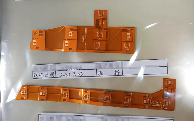
Flexible and rigid-flex circuits are typically the first choice for PCB designers when they need to save space, reduce weight, or eliminate bulky connectors.
They have driven the rapid growth of micro-electronic devices, ranging from medical wearables and drone systems to rugged aerospace applications.
However, as application demands continue to rise, even the most optimally designed flexible circuits are beginning to face challenges.
In many cases, the issues do not stem from routing or signal flow, but rather from EMI (electromagnetic interference), localized heat buildup, and mechanical stresses generated during use—factors that often determine whether a design will simply “work” or operate reliably in real-world environments.
Today, we’ll explore three powerful tools that can significantly enhance the design of flexible and rigid-flex circuits:
EMI shielding, thermal management, and mechanical stiffeners. Each adds a certain degree of complexity, but when used appropriately, they can deliver significant improvements in performance, durability, and reliability.
Key Points
Even if the routing and signal flow appear sound on paper, flexible and rigid-flex circuits still face real-world challenges such as EMI, heat buildup, and mechanical stress.
EMI shielding (copper mesh, silver ink, or shielding film) can control electromagnetic radiation, but it increases thickness and rigidity; therefore, it must be properly laid out, grounded, and designed in collaboration with the manufacturer.
Effective thermal management relies on stack-up planning, as well as tools such as heat-dissipating vias, thermal interface materials (TIM), and aluminum-backed stiffeners to dissipate heat from high-density component areas.
Mechanical stiffeners (FR4, polyimide, or metal) are critical for reliability and manufacturability; they reinforce component and connector areas, improve assembly operations, and avoid interfering with flex zones.
Shielding
Shielding is typically used in designs where there is a risk of electromagnetic radiation, which can occur in flexible designs lacking a complete ground plane. Adding shielding to specific areas of the design helps suppress excessive radiation from those areas.
Flexible circuits can employ a variety of shielding methods:
- Cross-hatched copper layers: These can serve as shielding within a flexible stack-up. The larger the openings in the grid, the poorer the shielding effectiveness, but the greater the flexibility—and vice versa.
- Silver ink shielding: Applied to the surface via screen printing, it is lightweight and flexible but has slightly lower conductivity.
- Shielding film: A pre-fabricated absorptive material containing metal particles and featuring an adhesive backing that can be applied directly to the surface of a flexible circuit; it is suitable for space-constrained designs.
Please note that shielding is not the only solution to radiation issues; it is best to first identify the root cause of the problem and attempt to resolve it.
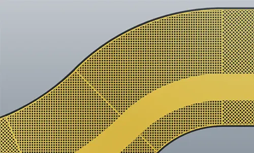
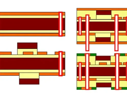
Fig 1 Planar grid image for simulation
However, shielding still offers advantages, and the choice of method depends on the application’s electrical performance and mechanical requirements.
Regardless of the technology used, it is essential to ensure that the shield is properly grounded and seamlessly integrated into the design.
It is also important to remember that shielding increases thickness and stiffness, limiting the range and radius of bending.
Therefore, it is best to apply shielding in areas close to the components, as bending is not possible near solder joints anyway.
Be sure to model these effects early on and work closely with the manufacturer to avoid surprises during production or assembly.
Thermal Management
In the past, thermal performance was a concern only in power electronics, but that is no longer the case.
As component density increases and package sizes shrink, even low-power flexible circuits may face thermal challenges—especially in rigid-flex boards, where active components are concentrated in the rigid section but heat spreads throughout the entire assembly.
Designers can employ various tools to achieve effective thermal management:
- Thermal vias: Help conduct heat from critical components to internal copper layers or external heat dissipation structures.
- Thermal interface material (TIM): Transfers heat from components to a heat sink or enclosure.
- Ribs with aluminum backing: Not only increase structural strength but also act as passive heat sinks.
Thermal management in flexible designs is often more challenging. Polyimide and thin adhesives perform well in terms of thermal stability but have poor thermal conductivity.
Even if they can withstand high temperatures, they cannot effectively dissipate heat.
Therefore, proper stack planning is crucial.
Increasing copper thickness, adjusting component placement, or adding passive heat sinks can all help alleviate hot spots.
It is essential to communicate thermal requirements with the manufacturer during the design phase, as material thickness and lamination processes can affect thermal performance.
Reinforcing Ribs
Designers often overlook mechanical stiffeners when developing flexible and rigid-flex circuits. However, these structural reinforcements significantly improve performance, especially during assembly and throughout the product’s operational life.
Mechanical stiffeners reinforce areas that require additional support, such as:
- Mount components such as BGAs and QFNs in these areas.
- Areas with ZIF connectors or press-fit contacts.
- Areas subjected to surface-mount or reflow processes.
- Protect these areas from bending during installation and operation.
Common reinforcement materials include:
- FR4: Commonly used; mechanical properties are compatible with rigid boards.
- Polyimide: Lightweight and more flexible, yet still provides increased rigidity.
- Metal (aluminum or stainless steel): High strength, and also aids in heat dissipation.
The layout of the stiffeners is critical. Keep stiffeners away from bending areas, and align them with openings in the solder mask or cover film when using adhesives.
Designers can use stiffeners with different thicknesses in specific areas to achieve the optimal balance between flexibility and strength.
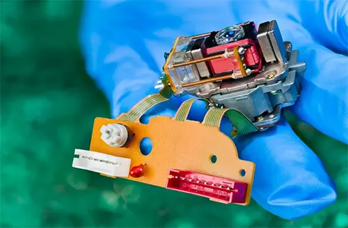
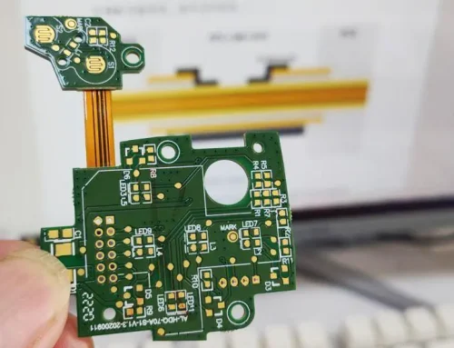
Fig 2 Reinforcing ribs can also improve the assembly process
Comprehensive Considerations
Shielding, thermal management, and mechanical reinforcements often determine whether a design can operate reliably in real-world environments—not just meet specifications on paper.
These are not after-the-fact fixes, but design elements that ensure long-term performance and reliability.
When designing flexible or rigid-flex circuits, it’s worth asking yourself a few questions:
- Will high electromagnetic interference or high edge rates affect the circuit?
- Do the enclosure dimensions or component weights pose thermal management challenges?
- Is the design easy to manufacture and capable of stable, long-term operation?
The answers to these questions will guide you in adopting one or more of the improvement measures mentioned above.
Conclusion
Flexible and rigid-flex PCBs provide significant advantages in compact, lightweight electronic designs, but achieving long-term reliability requires more than an optimized circuit layout.
Ignoring electromagnetic interference, heat accumulation, and mechanical stress during the early design stage can reduce overall circuit performance.
Addressing these challenges from the beginning helps ensure reliable operation and prevents potential performance issues later in the product lifecycle.
Designers can significantly improve signal integrity, thermal performance, assembly quality, and product durability by selecting the right EMI shielding solution.
They can further enhance overall reliability by optimizing thermal management strategies and installing mechanical stiffeners in areas that require structural support.
Each solution introduces its own design trade-offs, including increased thickness, reduced flexibility, or added manufacturing complexity, making careful planning essential.
The most successful flexible circuit designs consider these factors from the beginning rather than treating them as post-design fixes.
Close collaboration with the PCB manufacturer during material selection, stack-up development, and manufacturability review helps ensure that the final product meets both electrical and mechanical requirements.
By balancing flexibility with shielding, heat dissipation, and structural reinforcement, engineers can create flexible and rigid-flex circuits that deliver reliable performance throughout their service life, even in demanding applications such as medical devices, automotive electronics, aerospace systems, and industrial equipment.