
High-Frequency High-Speed FPC Materials for 6G (Part I)
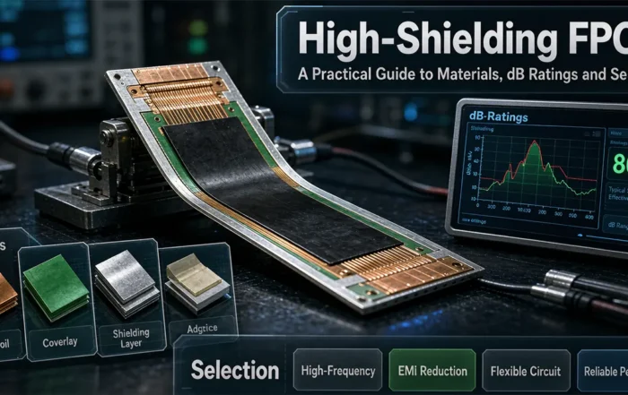
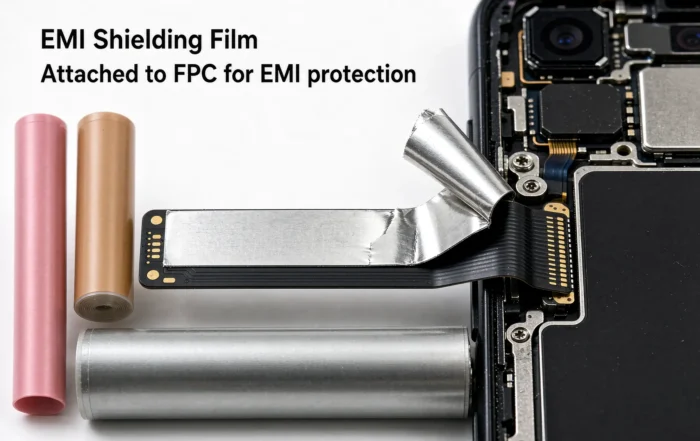
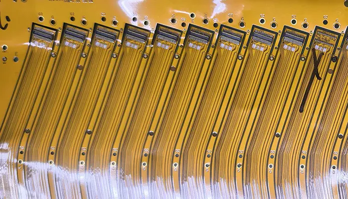
A high-frequency high-speed FPC is a flexible printed circuit built to carry fast signals with low loss. For 6G, designers pair low-Dk and low-Df dielectrics with microstrip or stripline stack-ups. This guide explains the material choices behind 6G FPC materials and how MPI and LCP for high-speed FPC fit the picture.


6G FPC Materials: Why Dielectric Loss Now Matters
6G is expected to become commercially available around 2030. It will deliver a quantum leap in performance. Transmission speeds will increase to 50 times those of 5G. Latency will decrease to one-tenth of 5G levels. In addition, connection density, mobility, and positioning accuracy will reach significant breakthroughs.
That evolution will strongly drive cutting-edge applications. Examples include native AI, VR devices, Level 5 autonomous driving, and collaborative robots. However, it also places higher demands on the underlying hardware.
As a key signal carrier, the flexible printed circuit board (FPCB) plays a crucial role. Therefore, enhancing transmission performance at high frequencies and speeds is important. Reducing transmission losses matters just as much.
6G-Driven High-Speed FPC Design and Material Selection


The most common stack-up designs for high-frequency, high-speed FPCs use microstrip or stripline configurations. The choice between the two sets how much interference the trace sees. It also sets how much energy the trace radiates.
Microstrip vs. Stripline in High-Speed FPCs
In a stripline design, the transmission line is fully encapsulated by the dielectric substrate. Reference ground planes sit above and below it. This configuration offers strong signal immunity to interference and minimal electromagnetic radiation. Therefore, it is generally suitable for frequencies above 10 GHz.
In contrast, a microstrip is a semi-exposed transmission line. Its reference ground plane sits only on the underside. It is susceptible to external interference and tends to radiate energy outward. As a result, it is generally suitable below 10 GHz.
How Signal Loss and Dk, Df Drive Material Choice
In general communication technology, signal transmission loss (TL) splits into conductor loss (TLC) and dielectric loss (TLD). The relationship between TLD and the dielectric constant (Dk) and dielectric loss (Df) of the material is given by a formula. In that formula, K is a coefficient, f is the frequency, and c is the speed of light.
Signal transmission delay (Td) also depends on the material. The relationship is Td = K x Dk^0.5, where K is a coefficient. Therefore, Dk controls delay. Df controls how much energy the dielectric absorbs.
Both microstrip and stripline expose the same critical interface. The insulating dielectric touches the metal conductor layer directly. Its Dk and Df values play a decisive role in signal transmission quality and the degree of signal loss.
MPI and LCP for High-Speed FPC: What Designers Compare
Once a design targets higher frequencies, the dielectric layer often becomes the limiting factor. MPI and LCP for high-speed FPC are the film families engineers evaluate at that point. Both are judged on dielectric behavior first, not mechanical strength alone. The test is simple: check Dk for delay and Df for loss.
FPC Material Systems: FCCL, CVL, and BS
Common FPC materials mainly include flexible copper-clad laminate (FCCL), cover film (CVL), and bare film (BS). Their typical laminate structures matter to signal integrity. The reason is direct: the dielectric layer sits against the copper. Also, the dielectric properties of that layer set the loss floor for the whole stack-up.
What 6G Applications Demand From Flex Circuits
The applications behind 6G share one trait. They need many high-speed links inside small, moving packages. For example, VR devices and collaborative robots both bend and flex during use. Level 5 autonomous driving adds strict latency limits.
Therefore, material selection cannot be separated from mechanical design. A low-loss dielectric helps only if the stack-up stays uniform after bending. Next, the trace geometry must match the chosen dielectric. Otherwise, impedance shifts and loss rises.
Design Checks Before Choosing a Laminate
Start with the frequency band, because it narrows the stack-up choice. Next, confirm whether stripline shielding is required above 10 GHz. Then compare candidate dielectrics on Dk and Df. Also confirm that the FCCL, CVL, and BS layers stay consistent.
Finally, validate the finished flex circuit, not just the datasheet. Bending, lamination, and assembly all change the dielectric environment. Keep design margin for those shifts.
FAQ
What is a high-frequency high-speed FPC?
A high-frequency high-speed FPC is a flexible printed circuit designed to carry fast signals with minimal loss. It uses controlled stack-ups, such as microstrip or stripline, plus low-loss dielectric materials. Its Dk and Df values decide signal delay and signal loss.
Why does Df matter more than Dk at high frequency?
Dk sets signal delay, so it stays relatively stable as frequency rises. Df describes dielectric loss, and its effect grows with frequency. Therefore, at higher bands, Df dominates the dielectric loss term in the transmission loss formula.
Is stripline or microstrip better for 6G FPC materials?
Neither is universally better. Stripline encloses the trace in dielectric with ground planes above and below, so it resists interference and radiates little. It is generally suitable above 10 GHz. Microstrip is semi-exposed and simpler, and it is generally suitable below 10 GHz.
What FPC materials are used in these stack-ups?
Common FPC materials include flexible copper-clad laminate (FCCL), cover film (CVL), and bare film (BS). The dielectric layer in contact with the copper conductor sets the electrical behavior. MPI and LCP for high-speed FPC are among the film options evaluated for lower-loss dielectrics.
Related Posts
- High Frequency Flexible PCB Impedance Control: Techniques and Design Guide — Related article
- Design of Automatic Assembly Equipment for Flexible Circuit Board — Related article
- High-Frequency FPC Materials Guide — Related article
- High-Frequency Rigid-Flex PCB Manufacturing — Related article
- PTFE Blind Via Processing for High-Frequency FPC — Related article





