FPC Reinforcement Guide: Why Flexible Printed Circuits Need Stiffeners

FPC Reinforcement Guide: Why Flexible Printed Circuits Need Stiffeners
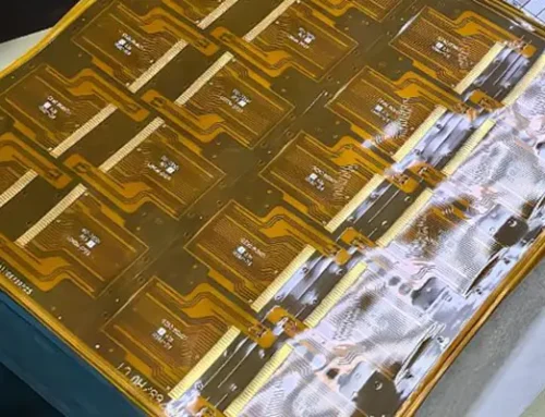
FPC reinforcement adds a stiffener layer to a flexible printed circuit so the part holds its shape and survives handling. Without it, thin flex circuits bend too easily near connectors and component pads. Therefore, FPC reinforcement protects solder joints, controls local stiffness, and keeps the board flat during SMT assembly.
Why FPC Reinforcement Matters in Flex Circuit Design
Flexible printed circuits are thin by design, and that thinness is often the whole point. However, some areas of the same board must stay flat. Connector fingers, side keys, and component pads all need a firm base.
Also, assembly adds stress. SMT assembly applies heat and pressure, so an unsupported flex area can warp or shift. As a result, reinforcement improves both mechanical strength and assembly yield, not just the look of the part.
FPC Stiffener Materials: Choosing the Right Support Layer

PI Reinforcement

steel sheet Reinforcement
FPC stiffener materials decide how a reinforced area behaves in use. Each option offers a different balance of stiffness, thickness, heat resistance, and cost.
- Polyimide (PI): the same film family used in PI-based flexible circuits, so it keeps the stack thin.
- PET: a practical choice when soldering heat stays low and cost is the main concern.
- Rigid copper clad laminate: a rigid CCL grade that gives a flat, firm surface under connectors and SMT pads.
- High-frequency stacks: LCP and MPI films appear in high-frequency FPC designs where impedance control also matters.
Choosing between them depends on the application. For example, a display FPC in a phone needs a very thin stiffener, while a rigid-flex board in a medical device can accept a thicker one. In addition, the material must survive the same lamination process as the rest of the stack.
Where Reinforcement for Flexible Printed Circuits Is Required
Reinforcement for flexible printed circuits is not needed everywhere. It belongs where a soft circuit meets a hard interface or a moving joint.
Connector, keypad, and soldering zones
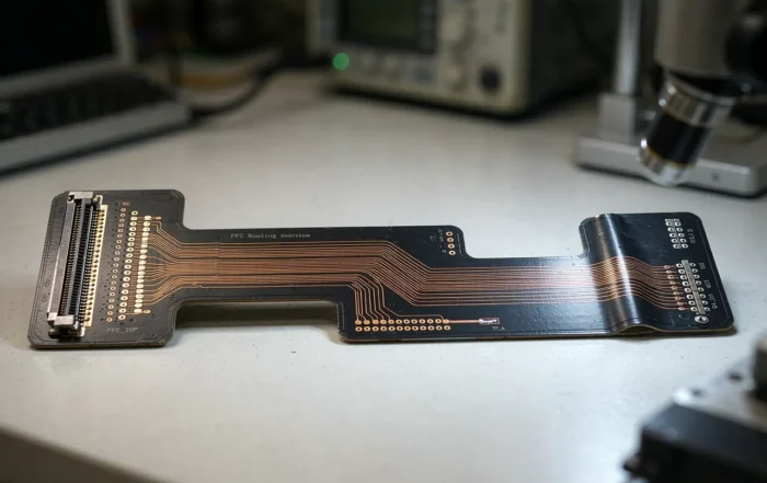
Connector fingers, side key FPC, and pad areas need a flat surface for insertion and reflow. Without support there, fingers can lift or crack during handling.
Long, hinge, and dynamic circuits
Flip phone hinge FPC, ultra-long flex PCB, transfer FPC, display FPC, and sensor FPC pass through repeated bending or long routing. Here the stiffener stays at the fixed ends, never inside the bending zone.
Board-to-board and rigid-flex joints
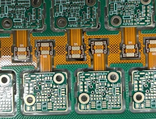
Rigid-flex PCB for medical devices and other rigid-flex builds use reinforcement at the transition between the rigid and flexible sections. This keeps the joint stable while the tail stays free to move.
How FPC Reinforcement Fits the Manufacturing Process
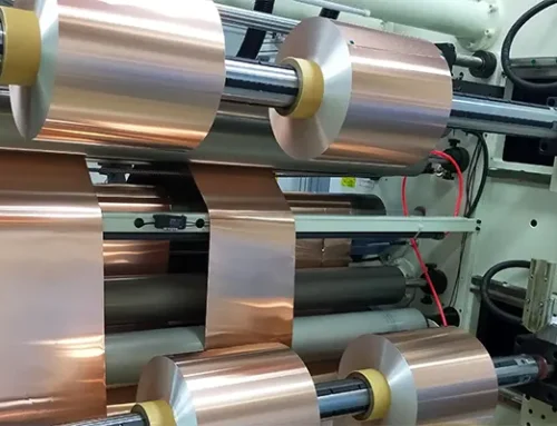
Reinforcement is one step inside a longer flow. The process starts with flexible material preparation and cutting, then moves through drilling, copper plating, and etching. Next comes lamination, then surface finish, and finally testing.
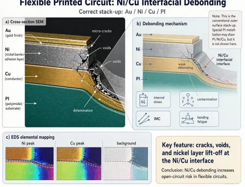
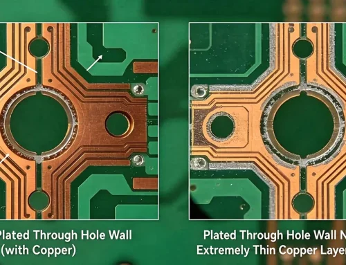
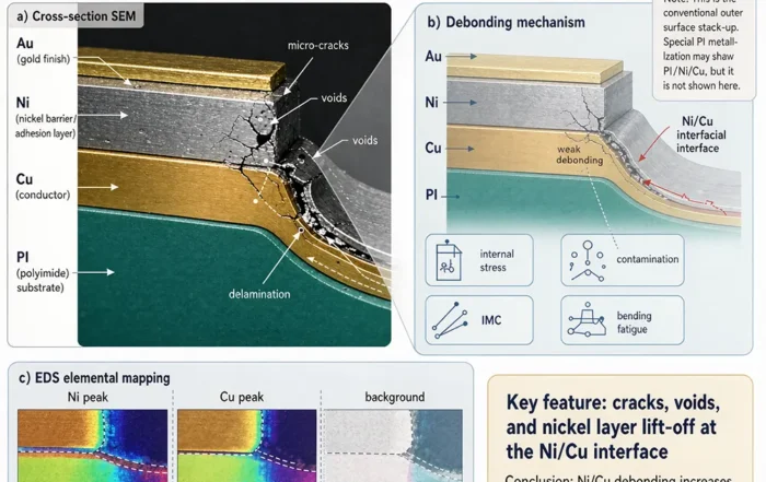
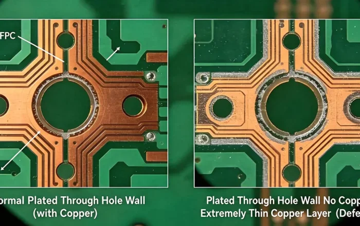
Because lamination bonds the stiffener to the circuit, process control matters. A weak bond may appear later as delamination or as nickel-copper adhesion failure. Therefore, factories check hole wall quality and bond strength before shipping.
Design Rules and Quality Checks for FPC Reinforcement
Good reinforcement design follows a few simple rules:
- Keep the stiffener inside the board outline, with no sharp corners.
- Leave a clear transition between stiff and flexible zones.
- Match the stiffener area to the connector footprint, not the whole board.
- Plan test points before lamination, not after.
Testing supports the design. Common checks include flex testing, impedance control on high-frequency parts, and visual inspection of drilled hole walls. In addition, reviewing common flexible PCB design mistakes early is far cheaper than fixing them after lamination.
Who Builds Reinforced Flex Circuits
Gekun has manufactured flexible PCBs since 2014 from Shenzhen, China. The product range covers single-sided flex, double-sided flex, multilayer flex, rigid-flex PCB, and flex PCB assembly (FPCA). Typical markets include mobile phones, consumer electronics, medical devices, industrial automation, and automotive.
FAQ
What is FPC reinforcement?
FPC reinforcement is a stiffener layer added to selected areas of a flexible printed circuit. It gives local rigidity to connector fingers, keypads, and SMT pads while the rest of the circuit stays bendable. The layer is bonded to the circuit during lamination.
Which FPC stiffener materials are used most often?
The common FPC stiffener materials are polyimide (PI) film, PET film, and rigid copper clad laminate. PI suits thin, heat-resistant designs. PET fits low-heat, cost-sensitive parts, and rigid CCL provides the flat surface that connectors and SMT pads need. LCP and MPI appear in high-frequency designs.
Does reinforcement for flexible printed circuits reduce flexibility?
Reinforcement for flexible printed circuits reduces flexibility only where it sits. Designers keep the stiffener out of bending zones, such as a hinge FPC or an ultra-long flex PCB. That way the moving section stays flexible while the fixed ends stay rigid.
Related Posts
- Rigid Flex PCB Manufacturing: A Process Overview – GekunFlex — Related article
- Rigid-Flex PCB manufacturing Guide — Related article
- FPC Design Guide — Related article
- Flex PCB Materials, Layup Structures, and Production Processes — Related article
- Innovative Flexible Circuit Manufacturing — Related article