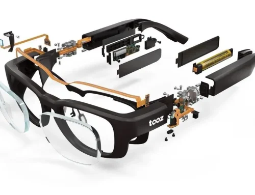
“Magic of Flexibility” Behind Foldable Phones: A Comprehensive Guide to the Secrets of FPC Layering Design
Have you ever wondered why foldable smartphones can be opened and closed tens of thousands of times without the screen breaking? Or why can such a small smartwatch pack in so many sensors?
The biggest contributor behind all this is the flexible printed circuit board (FPC)—often referred to as the “flexible nervous system” of electronic devices.
Thanks to its flexibility, lightness, thinness, and compact size, the FPC has long been an indispensable core component across various industries, including smartphones, automotive electronics, and aerospace.
However, to ensure that FPCs remain stable and reliable under harsh conditions—such as repeated bending, high temperatures, and high pressure—their laminate design is the key to success.
Today, we’ll take an in-depth look at the core logic, key considerations, and industry best practices behind FPC laminate design, taking you into the cutting-edge world of flexible circuits.
What Is FPC Laminate Design? It’s More Than Just “Stacking Materials”
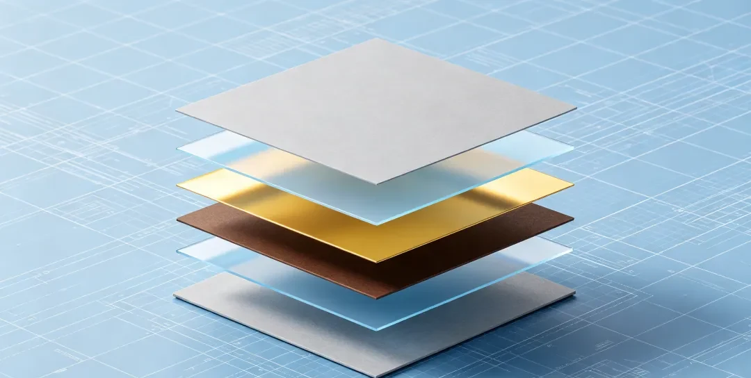
FPC laminate design may sound abstract, but simply put, it involves systematically planning the sequence, thickness ratios, and overall structure of materials such as the substrate, conductive layers, adhesives, cover films, and reinforcing plates.
Its ultimate goal is to achieve three key balances:
- Flexibility vs. mechanical strength
- Electrical performance vs. durability
- High reliability vs. cost control
A well-designed laminate can enable an FPC to withstand over a million bending cycles. In contrast, a poorly designed one may curl, delaminate, or even break before it even leaves the factory.
6 Key Factors That Determine the Success or Failure of an FPC
Material Selection Is the Foundation: There Is No “Best” Material, Only the Most Appropriate One
The “body” of an FPC is composed of various materials; choosing the right materials means the design is already halfway to success.
1) Insulating Substrates:
Polyimide (PI): The premier material, offering high-temperature resistance (>250°C) and a combination of flexibility and toughness, making it the top choice for automotive and medical applications.
Polyester (PET): The best value for money, but with low temperature resistance (~105°C), making it suitable for static applications such as charging cables.
Liquid Crystal Polymer (LCP): The darling of the 5G era, with extremely low signal loss, making it the perfect match for millimeter-wave radar.
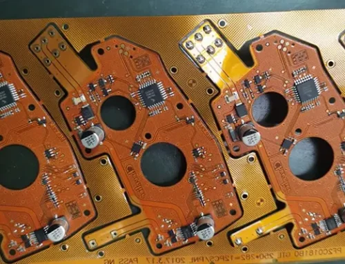
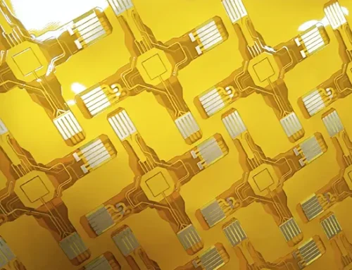
2) Conductive Copper Foil:
Rolled Anodized (RA): Naturally flexible and resistant to bending, it is the “chosen one” for dynamic bending applications such as foldable screens and robot joints.
Electrolytic Copper (ED): Engineers use it in static applications requiring only a single bend because it is inexpensive but loses performance after just one bend.

Fig 1
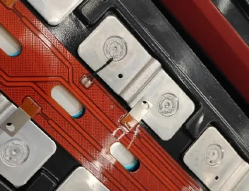
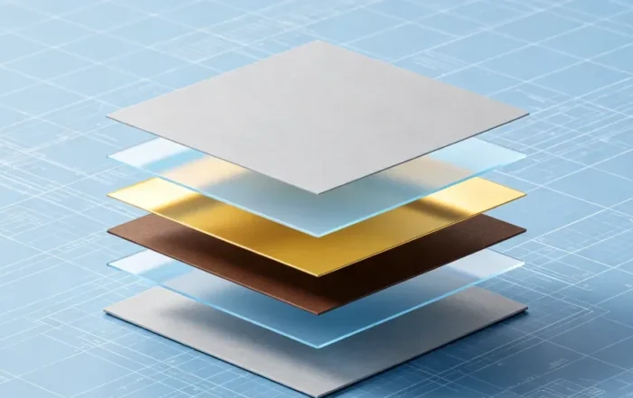
Neutral Axis Principle: The Secret to Bending Without “Damaging the Core”
Imagine bending a business card: the layer in the middle experiences neither tension nor compression—this is the neutral axis. In FPCs, positioning the copper conductor layer precisely on the neutral axis is the core principle for ensuring bending durability.
Symmetry Is Key: Designers must adopt a top-and-bottom symmetrical structure in double-layer or multilayer FPCs to center the neutral axis and prevent the board from curling.
Conductors Near the Center: In multilayer designs, concentrate signal layers as close to the neutral axis as possible to keep stress away from the fragile conductors.

Fig 2
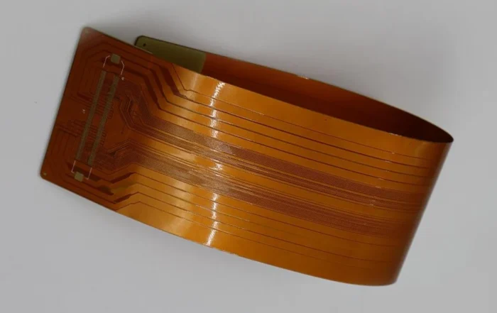
Bending Scenarios: Static vs. Dynamic—A World of Difference
Static Bending: A single bend, such as a flex cable that remains stationary once installed in a smartphone. The minimum bend radius need only be ≥6 times the board thickness.
Dynamic Bending: Bends daily and repeatedly, such as at the hinge of a foldable screen. The minimum bend radius must be ≥10 times the board thickness.
Restricted Areas: Designers should keep through-holes, pads, and components out of the bending area. Traces must be perpendicular to the bending axis and evenly distributed.

Fig 3
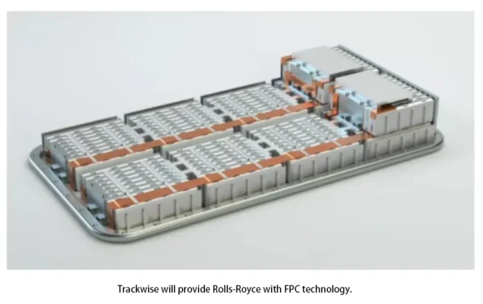
Electrical Performance: Not Just Connectivity, but Reliability
Impedance Control: High-frequency signals (such as USB and HDMI) require a precise impedance of 50Ω or 100Ω. Designers achieve this by adjusting the trace width, trace spacing, and dielectric layer thickness.
Electromagnetic Shielding: Designers employ an adjacent signal layer–ground layer structure to create a Faraday cage around the signal lines and prevent mutual interference.

Fig 4
Layer Planning: More Isn’t Always Better
Single-layer: Ultimate flexibility and the simplest signal transmission.
Double-layer: The most widely used “all-purpose” option, offering balanced performance with a symmetrical structure.
Multi-layer (4–8 layers): The choice for high-density routing, though it sacrifices some flexibility.
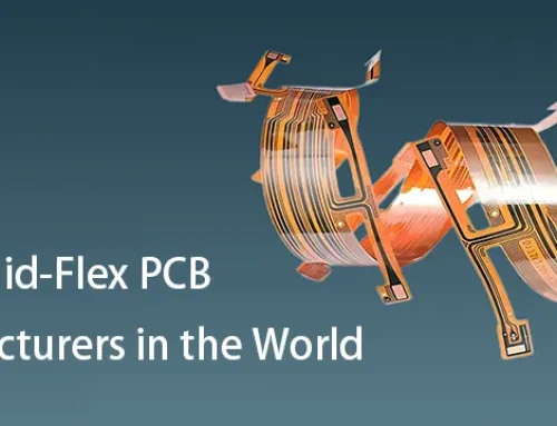
Rigid-flex boards: The rigid section (FR4) supports the chips, while the flexible section (PI) enables 3D assembly, making it the ultimate solution for complex products.
Manufacturing Processes and Costs: Practicality Is What Matters Most
No matter how beautiful the design, it’s useless if the factory can’t produce it or if the cost is exorbitant. A good multilayer design must:
Be compatible with the factory’s existing lamination, etching, and drilling capabilities.
Prioritize cost-effectiveness; where performance allows, use standard-thickness materials and minimize the use of special processes.
Engineers should validate the design according to international standards such as IPC-2223.
Industry Best Practices: How the Pros Do It
Classic Laminate Solutions
Single-layer static FPC: PI film + adhesive + copper foil + PI substrate + bottom PI film, total thickness approximately 140 μm; cost-effective and durable.
Double-layer dynamic FPC: Symmetrical top and bottom PI films + calendered copper of equal thickness, total thickness approximately 160 μm, with the neutral axis perfectly centered.
Rigid-flex board: FR4 multilayer board for the rigid area, ultra-thin PI for the flexible area, with a “gradual window” transition in the interface zone to prevent stress concentration.
Design Guidelines
Symmetry, symmetry, and more symmetry: This is the “golden rule” of FPC design.
Minimize elements in bend zones: Remove all non-essential components (copper layup, vias, silk screen) except for necessary traces.
Precise Reinforcement: Designers should apply reinforcement only at stress points such as connectors and solder areas and chamfer the edges.
Simulation First: Use software like ANSYS to perform stress and impedance simulations before production; this can save millions in trial-and-error costs.
Three Major Pitfalls to Avoid
Asymmetric layering: This causes the finished product to curl up like a “squid,” making it impossible to mount.
Using ED copper for dynamic bending: It will break after just a few bends—this is the most common rookie mistake.
Ignoring the minimum bend radius: Statistics show that 78% of FPC failures stem from this!
Future Trends: FPCs Will Become “Thinner, Faster, and Stronger”
With the explosive growth of foldable screens, 5G, autonomous driving, and implantable medical devices, FPC laminate design is evolving in three major directions:
Ultra-thin:
The widespread adoption of adhesive-free substrates, ultra-thin PI, and copper foil is driving total thickness below 50 μm—thinner than a human hair.
High-Frequency and High-Speed Capabilities:
Low-loss materials such as LCP and MPI (modified polyimide) are becoming mainstream, with laminate designs pursuing ultimate impedance accuracy and integrated shielding.
High Reliability:
The bend life requirements for automotive-grade and medical-grade FPCs are moving from “100,000 cycles” to “1 million cycles,” with symmetrical design and stress optimization at the core.
Integration:
Manufacturers are increasingly adopting rigid-flex boards and are even embedding resistors and capacitors directly into FPCs.
FPC, this seemingly unremarkable “film,” is in fact a convergence of materials science, structural mechanics, electrical engineering, and precision manufacturing.
An excellent laminate design can achieve a perfect balance between flexibility and strength, as well as performance and cost, even under the grueling test of repeated bending.
For manufacturers, understanding the core logic of laminate design is akin to mastering the “driver’s manual” for FPC.