Power and Energy Storage FPCs: Manufacturing Process, Materials, Trends, and Future Innovations


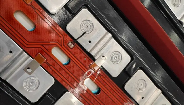
FPCs (flexible printed circuit boards) for power and energy storage applications are critical components in new energy vehicles and energy storage systems (ESS).
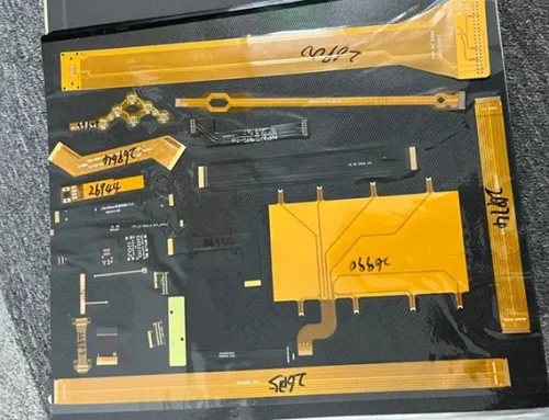
They are primarily used for sampling, temperature monitoring, and signal transmission within battery modules (i.e., as replacements for BMS sampling harnesses or FFCs).
Given their harsh operating environments—which include high voltage, high current, vibration, and the potential for thermal runaway—these FPCs must meet extremely high standards for reliability, safety, and durability.
The following section details the core manufacturing processes and procedures, highlighting key differences from FPCs used in consumer electronics.
Special Requirements for FPCs in Power and Energy Storage Applications
Before examining the processes, it is essential to understand the specific requirements that dictate material and process selection:
1. High Voltage/High Current: Must withstand system voltages of up to 800V or higher and possess strong overcurrent capacity.
2. High Reliability & Safety: Zero tolerance for short circuits or open circuits; extremely high insulation and arc resistance are required.
3. High-Temperature and High-Humidity Resistance: Wide operating temperature range (-40°C to 125°C+); must withstand high-temperature aging and thermal shock.
4. Resistance to Electrolyte Corrosion: Must be able to resist corrosion from potential electrolyte leaks (e.g., LiPF6) within the battery pack.
5. Balance of Mechanical Strength and Flexibility: Requires sufficient rigidity for easy installation, yet must possess localized flexibility to accommodate cell expansion and vibration.
6. Flame Retardancy: Must use high-grade flame-retardant materials (e.g., UL94 V-0) to prevent fire spread.
Core Production Process Flow
Sheet Cutting → Drilling → Copper Plating → Dry Film Application/Exposure/Development → Etching → Film Stripping → AOI Inspection → Cover Film Application → Laminating → Surface Treatment → Reinforcement Lamination → Printing (Solder Mask, Markings) → Electrical Testing → Trimming → Final Inspection/FQC → Packaging
Detailed Step-by-Step Explanation of Key Processes
1. Material Selection (Starting Point)
Substrate (PI Film): Thicker PI films with better dimensional stability and higher heat resistance are typically used, such as 25μm, 50μm, or even thicker.
Copper Foil: Rolled Anodic (RA) copper is used instead of Electrolytic (ED) copper.
RA copper offers excellent resistance to bending fatigue and is more suitable for dynamic flexible applications.
Copper thickness is typically 1 oz (35 μm) or 2 oz (70 μm) to meet high-current requirements.
Cover Film (CVL) and Adhesive Layer: High-performance polyimide cover film is used, and the adhesive system must be heat-resistant and resistant to electrolyte corrosion.
This is one of the key material differences compared to FPCs for consumer electronics.
Reinforcement Materials: FR4, aluminum sheets, stainless steel sheets, or thick PI are used for reinforcement in areas such as connector terminals and mounting holes to provide support and rigidity.
Solder Mask: Flexible solder mask is used, featuring high insulation, corrosion resistance, and flame retardancy.
2. Pattern Formation (Inner Layer Process)
Cutting and Drilling: Rolled raw material is cut to the size of production boards. Through-holes are created using laser drilling or mechanical drilling.
Copper Plating: Copper is chemically deposited and electroplated inside the holes to achieve electrical interconnection between layers. High reliability is required, and the uniformity and adhesion of the copper plating are critical.
Dry Film Application and Exposure: A photosensitive dry film is applied to the copper surface. Using laser direct imaging (LDI), UV light is used to expose the circuit pattern onto the dry film.
Development and Etching: The unexposed areas are washed away during development (negative process), exposing the copper to be etched. An acidic etching solution is then used to remove the copper from the non-circuit areas, forming a precision circuit.
Stripping and AOI: The dry film protecting the circuit is removed, and Automated Optical Inspection (AOI) is used to perform a 100% inspection for defects such as open circuits, short circuits, gaps, and burrs.
3. Laminating and Covering
Applying the Cover Film: A cover film with pre-cut windows (exposing the pads) is precisely aligned and applied to the etched circuit.
Laminating: A high-temperature, high-pressure press is used to firmly bond the cover film to the substrate.
Precise control of temperature, pressure, and time is critical, as it directly affects heat resistance and delamination resistance.
4. Surface Treatment
Purpose: To protect the exposed copper surface of the pads from oxidation and provide a surface suitable for soldering and connection.
Common Processes:
Electroless Nickel-Palladium-Gold (ENEPIG): The most mainstream and reliable process.
The nickel layer acts as a barrier, the palladium layer prevents nickel corrosion, and the gold layer provides excellent contact and solderability.
It offers the best corrosion resistance and solder joint reliability.
Electrolytic Hard Gold: Used on critical connector contacts; offers excellent wear resistance.
Oxidation-Stabilized Phosphate (OSP): Less commonly used due to relatively poor durability.
5. Reinforcement Lamination
Using a high-temperature laminating machine, the reinforcement sheet is precisely laminated to the designated area on the back of the FPC. This ensures a strong bond, free of air bubbles, and accurate positioning.
6. Printing and Marking
Solder Mask Printing: Flexible solder mask ink is printed on areas where soldering is not required to provide secondary protection and insulation.
Character Printing: Component part numbers, version numbers, polarity indicators, and other markings are printed.
7. Electrical Testing and Final Processing
Electrical Testing (Fly-Probe Testing or Test Fixture): 100% electrical testing is performed to verify circuit continuity (no open circuits) and insulation (no short circuits). This is a critical step in ensuring safety.
Contour Cutting: Performed using laser cutting or steel die punching.
Laser cutting offers high precision and is stress-free, making it suitable for small batches, high precision, and irregular edges.
Die punching is highly efficient and cost-effective, making it suitable for high-volume production.
Due to the complex contours of power FPCs (with terminals and irregular shapes), both processes are often combined.
Cleaning (Debris Removal): Removal of debris and contaminants generated during cutting.
8. Final Inspection and Packaging
Final Visual Inspection (FQC): Manual or AOI-assisted inspection of appearance, scratches, contamination, and reinforcement lamination.
Critical Dimension Measurement: Measurement of critical dimensions such as terminal pitch and total length.
Packaging: Use of anti-static, crush-resistant, and moisture-proof materials; typically, each sheet is placed individually or on a tray to prevent bending and damage during transportation.
Key Process Differences from Consumer Electronics FPCs
| Feature | Power / Energy Storage FPC | Consumer Electronics FPC (e.g., Smartphones) |
|---|---|---|
| Material Grade | Automotive / Industrial Grade; high-temperature resistant, corrosion-resistant, high-Tg materials | Commercial grade, cost-sensitive |
| Copper Foil Type | Rolled Annealed Copper (RA), excellent flex resistance | Electro-Deposited Copper (ED), lower cost |
| Copper Thickness | Thicker (1–2 oz), capable of carrying high current | Thinner (0.5–1 oz) |
| Reliability Testing | Extremely stringent: High Accelerated Stress Test (HAST), thermal cycling (1000+ cycles), electrolyte immersion, high-voltage testing | Standard reliability testing |
| Safety Standards | Zero-defect target; functional safety considerations (ISO 26262), UL94 V-0 flame retardancy | Meets general safety requirements |
| Process Control | High Process Capability Index (CPK) requirements; Statistical Process Control (SPC), full-process traceability | Conventional process control |
| Test Coverage Rate | 100% electrical testing + multiple inspections | Primarily sampling-based testing |
Development Trends
Trend 1: Integration and Modularization — “All-in-One” FPC Modules
This is the most significant trend. FPCs are no longer merely substitutes for wire harnesses but have become intelligent carriers integrating multiple functions.
Functional Integration:
Integration of NTC/PTC:
Temperature sensors (thermistors) are directly mounted or printed onto the FPC to enable multi-point, precise temperature monitoring.
Integration of Fuses:
Current sensing circuits are designed on the FPC, or micro-fuses are directly integrated to provide overcurrent protection.
Integration of Voltage/Current Detection Circuits:
Through precise circuit design, more accurate voltage acquisition and balancing are achieved.
Integration of Communication Chips and Microcontrollers (MCUs):
Evolving into chip-integrated FPCs (FPC-SiP), enabling local data preprocessing and intelligent management, thereby reducing the load on the main BMS.
Structural Integration:
Integration with Copper/Aluminum Busbars:
Combining the FPC with power busbars to achieve integrated “signal + power” transmission, reducing connection points and improving space utilization.
Integration with structural components and insulating layers:
The FPC is laminated together with insulating films, thermal conductive adhesives, protective films, and other materials, simplifying the assembly process.
Impact:
Reduced component count, lower system complexity, improved reliability, and increased production efficiency.
Trend 2: Material and Process Upgrades — Addressing Extreme Challenges
To adapt to advanced battery technologies such as 800V high-voltage platforms, fast charging, and CTP/CTC, materials and processes are undergoing continuous innovation.
Material Innovations:
Higher-performance substrates:
Development of modified PI or new polymer films (e.g., LCP, suitable for high frequencies but costly) that offer higher temperature resistance (>150°C), superior insulation, and lower dielectric loss.
More reliable adhesives:
Improved resistance to electrolyte corrosion and enhanced bonding stability under long-term high temperatures.
Thicker Copper Foil and Roll-Forming Process Optimization:
Supporting high-current collection requirements of 300A+ while maintaining excellent flex resistance.
Thermally Conductive FPC:
Using thermal conductive adhesives or fillers in areas requiring heat dissipation to assist in cooling BMS chips or critical components.
Process Innovations:
Finer Circuit Lines:
Line widths and line spacings are becoming finer (e.g., 50μm/50μm) to integrate more functions.
Advanced Surface Treatments:
ENEPIG (electrolytic nickel-palladium-gold) has become the dominant standard due to its excellent corrosion resistance and soldering reliability, and is evolving toward thinner and more uniform coatings.
Additive Manufacturing/Printed Electronics:
Exploring the use of conductive silver paste to print portions of circuits or sensors, enabling more flexible, custom-shaped designs and low-cost manufacturing.
Trend 3: Intelligence and Digitalization — “Communicative” FPCs
FPCs will serve as the sensory nerve endings for monitoring the internal status of battery packs.
Distributed Data Acquisition:
Microprocessors integrated onto the FPC can perform preliminary data calculations and filtering, uploading processed information to enhance the system’s interference resistance and response speed.
State of Health (SoH):
Through integrated high-precision sensors, not only can voltage and temperature be monitored, but cell expansion (via flexible strain sensors) and internal pressure changes can also be indirectly detected, providing multidimensional data for battery health assessment.
Exploration of Wireless Transmission:
In specific application scenarios (such as replaceable battery packs or areas where wiring is difficult), research is underway to transmit collected data wirelessly via technologies like Bluetooth Low Energy (BLE), thereby eliminating the need for physical communication cables.
Trend 4: Standardized and Platform-Based Design
To reduce costs, shorten development cycles, and improve supply chain efficiency, the industry is driving the standardization of FPCs.
Interface Standardization:
Standardizing connector models, pin definitions, and communication protocols enables FPCs to adapt to the platforms of different battery manufacturers and vehicle manufacturers.
Modular Design:
FPCs are divided into distinct functional modules (such as data acquisition, balancing, and communication modules), allowing for a “building-block” style combination design tailored to different vehicle configurations.
Establishment of Industry Standards:
Industry consensus and standards are emerging regarding testing criteria, reliability requirements, and safety ratings for power/energy storage FPCs.
Trend 5: Extreme Cost Reduction and Green Manufacturing
Cost pressures are driving technological innovation while ensuring the highest levels of reliability.
Design Optimization:
Optimizing circuit designs through simulation to reduce the number of layers and minimize area, thereby achieving “subtraction for efficiency.”
Improved Manufacturing Efficiency:
Adopting larger panelization, promoting automation (such as fully automated laser cutting and AOI inspection), and optimizing process flows to improve yield and efficiency.
Localization of Materials:
Accelerating the substitution of key materials—such as high-performance PI film, specialty adhesive films, and calendered copper foil—with domestically produced alternatives is a core strategy for cost reduction.
Environmental Sustainability:
Compliance with environmental requirements such as RoHS and halogen-free standards, while exploring the use of recyclable or bio-based materials.
Conclusion and Outlook
The production of FPCs for power and energy storage applications essentially involves the enhancement and upgrading of traditional FPC manufacturing processes under ultra-high reliability requirements. Its core competitiveness lies not only in precise pattern fabrication capabilities but also in:
1. A deep understanding of and proficiency in applying specialty materials (such as corrosion-resistant adhesives and RA copper).
2. An extremely rigorous and stable process control system (CPK values for each stage).
3. Comprehensive and rigorous testing and validation capabilities (electrical, environmental, lifespan, and safety).
4. Complete traceability (from raw material batches to the final product).
In the future, FPCs for power and energy storage applications will evolve along two main trajectories: “structure-function integration” and “hardware-software synergy.”
They will transition from etched FPCs to die-cut FDCs. They will evolve from passive connection components into critical battery pack subsystems capable of active sensing, intelligent processing, and reliable execution.
Vision for the Ultimate Form: The emergence of a “smart battery skin”—a highly integrated FPC covering the surface of a cell or module.
This skin integrates all sensors, management chips, and communication units to monitor the battery’s “temperature, blood pressure, and pulse” in real time, while seamlessly coordinating with the battery pack’s “brain” (the main BMS).
It will serve as the cornerstone for ensuring battery safety, enhancing performance, and extending lifespan. This requires the deep integration of materials science, electrical engineering, semiconductor technology, and battery technology.
This is a high-end FPC market segment characterized by significant technical barriers and lengthy certification cycles, yet offering higher value.
With the development of the new energy vehicle and energy storage industries, its manufacturing processes continue to evolve toward higher integration (such as SIP-FPCs with embedded chips), higher voltage ratings, and stronger thermal management capabilities.