Rigid-Flex PCB: Rework Reliability, Storage Conditions, and Failure Analysis


A flexible printed circuit board (FPCB) is a printed circuit board made from a flexible substrate, which may not have a cover layer.
Rework Reliability of Rigid-Flex PCBs Under Different Storage Conditions
Compared to traditional rigid printed circuit boards, they are characterized by thinness, light weight, and the ability to bend and fold freely;
The ability to achieve three-dimensional interconnection is its essential characteristic, and it also allows for the separate routing of signals of different types and frequencies, significantly reducing mutual interference.
Rigid-flex PCBs are a type of specialized FPCB.
They are currently widely used in consumer electronics and medical devices, and are gradually being adopted in the aerospace and military sectors.
Miniaturization Trend and Structural Advantages
For a certain series of products, with the development of standardization, modularization, and miniaturization, rigid-flex PCBs with bending, torsion, and three-dimensional wiring capabilities are used to replace traditional wires, enabling rapid assembly of high-density electrical interconnections in small spaces.
Compared to wire soldering processes, the successful application of rigid-flex PCBs can resolve the challenges of complex cable routing in confined spaces, reduce the manufacturing difficulty associated with manual soldering, shorten production cycles, standardize electrical interconnections, and meet the demands of high-volume rapid manufacturing.
Electronic Assembly and Quality Control Challenges
In practical engineering applications of rigid-flex PCBs, the electronic assembly processes and methods determine product quality.
Current research in China on the impact of electronic assembly on rigid-flex printed circuit boards primarily focuses on: delamination of flexible boards after reflow soldering, which can be mitigated by selecting appropriate adhesive film thickness and lamination parameters based on product characteristics.
Under conditions where the external quality of solder joints is good, and the tin penetration rate is 100%, the soldering temperature range for rigid-flex boards in aerospace applications is 260–370°C, and the number of reworks should be less than three.
During the high-temperature hot-air leveling soldering process, the orientation of the HASL coating affects wrinkling and tearing anomalies in the flexible region.
Different materials in flexible circuits have inconsistent in-plane expansion coefficients and moduli in the X-Y plane.
Under the high-temperature stress of soldering, unequal tensile stresses arise between them; the higher the temperature, the greater the stress difference, and the higher the risk of delamination.
Rework Risks and Failure Mechanisms
However, when quality issues in rigid-flex printed circuit boards arise due to interconnections with other electronic components, rework of the rigid interconnection sections is required.
The reworkability of these sections is lower than that of traditional wires or cables, and failures in rigid-flex PCBs are prone to occur during the rework process.
There is limited research data on the causes of failure, and since rigid-flex PCBs are formed by laminating rigid and flexible materials, the different materials exhibit variations in heat resistance, thermal expansion coefficients, and water absorption.
Under the influence of thermal and external stresses during soldering and rework, this may lead to delamination, separation of plated-through hole walls from the substrate, and tearing of inner-layer conductors, resulting in inner-layer interconnect disconnection (ICD).
Therefore, based on the manufacturing and usage environments of a specific product series, this paper investigates the impact of storage conditions on the quality of rigid-flex printed circuit board (PCB) rework.
It conducts research on the soldering and rework processes of rigid-flex PCBs, along with microscopic inspection and evaluation. This work holds significant implications for promoting the large-scale application of rigid-flex PCBs in military electronic products.
Process Research and Experimental Validation
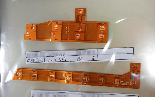
Overview of Test Samples
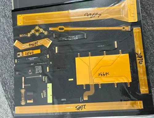
The rigid-flex PCBs selected for this study consist of multiple flexible layers that are not bonded together, ensuring high flexibility (see Figure 1).

Figure 1: Schematic diagram of the test specimen’s flexible layered structure
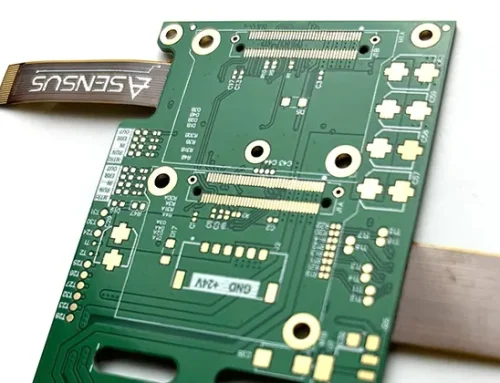
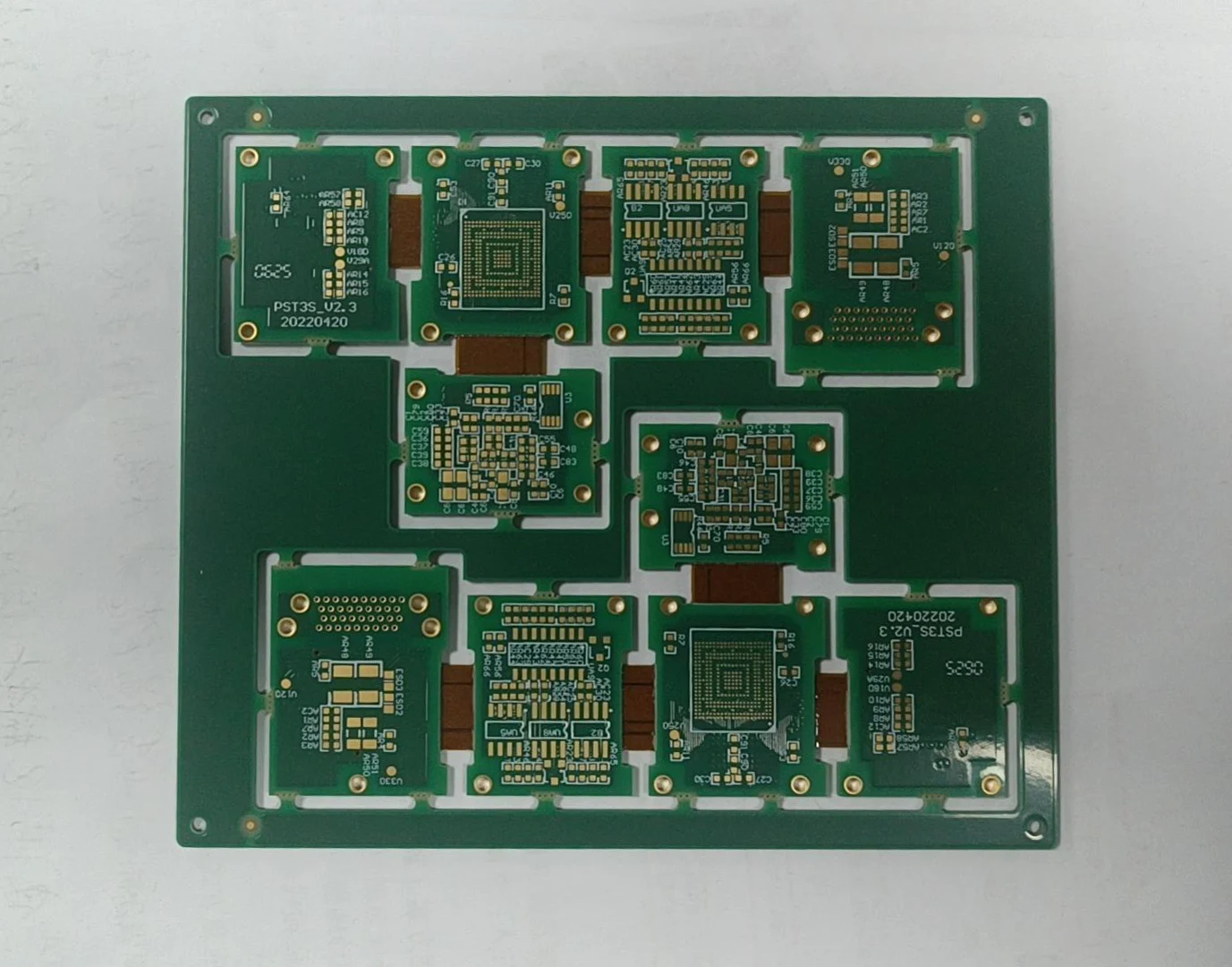
The rigid board is connected to the electronic components via a through-hole connector design (see Figure 2), and the pads are electroplated with gold to ensure the quality and strength of the solder joints.

Figure 2 Schematic diagram of through-hole mounting of the test specimen
Test storage conditions: According to QJ201B-2012 “Specifications for Rigid Single- and Double-Sided Printed Circuit Boards for Aerospace Use,” when multiple printed circuit boards are packaged together, they should be separated by neutral packing paper.
Generally, laminated plastic bags are used for vacuum-sealed packaging, with the pad coating layer consisting of electroless gold plating/ nickel plating on the pads; the PCBs should be stored in a clean container or box at a temperature of 10–35 °C and a relative humidity of no more than 75%.
SJ21513-2018 “Requirements for the Handling of Moisture-Sensitive Components Before Electronic Assembly” stipulates that the environment for handling moisture-sensitive components should maintain a temperature of (23±5)°C and a relative humidity of 45%–70%.
Based on the above standard and in consideration of the manufacturing cycle of a specific product series, if rigid-flex printed circuit board interconnect electronic components fail and require rework or repair, the storage conditions for rigid-flex printed circuit boards during the manufacturing process are tightened, with a specified temperature of (23 ± 5) °C and relative humidity below 40%.
Test Sample Classification and Inspection Requirements
The test specimens were divided into three categories, with the quantity determined in accordance with the selection criteria for qualification testing of a specific product series; three specimens were selected for each category.
These rigid-flex printed circuit board test specimens are military products. Each production batch includes test specimens for microtome sectioning; the batch of rigid-flex printed circuit boards is only released after the microtome sections are found to be qualified.
Additionally, each test specimen undergoes electrical connection testing after both soldering and desoldering to determine the specimen’s condition before microtomy, thereby eliminating interference factors introduced by the specimen itself, as well as the soldering and desoldering processes.
Test Specimens 001–003:
1) Rigid-flex boards were vacuum-dried and encapsulated at a temperature of (23±5)°C and humidity below 40%, then stored for 3 months;
2) Assembled and soldered (assembly cycle less than 1 day);
3) Electrical connections of the rigid-flex boards were tested, and all connections were found to be conductive;
4) Disassembled and desoldered;
5) Tested the electrical connections of the rigid-flex board; all connections were conductive.
Test Samples 004–006:
1) The rigid-flex board was vacuum-dried and encapsulated at a temperature of (23±5)°C and humidity below 40%, and stored for 3 months;
2) Assembled and soldered (assembly cycle less than 1 day); semi-finished product (rigid-flex board exposed) stored at (23±5)°C and humidity below 40% for 5 months;
3) Test the electrical connections of the rigid-flex board; all connections are conductive.
4) Disassembly and desoldering;
5) Testing of the rigid-flex board’s electrical connections: some connections are not conductive.
Test Samples 007–009:
1) Vacuum drying and potting of the rigid-flex board at a temperature of (23 ± 5) °C and humidity below 40%, followed by 3 months of storage;
2) Assembled and soldered (assembly cycle less than 1 day); finished product (rigid-flex board placed in a sealed space under positive pressure with 99.999% nitrogen, gas leakage rate less than 5×10⁻⁷ Pa·m³/s) at a temperature of (23±5)°C, humidity <40%, and stored for 5 months;
3) Test the electrical connections of the rigid-flex board; all connections must be conductive;
4) Disassemble and desolder the unit; 5) Test the electrical connections of the rigid-flex board; all connections must be conductive.
Test Procedures and Parameters
QJ3117A-2011A “Technical Requirements for Manual Soldering Processes of Aerospace Electronic and Electrical Products” defines the soldering process parameters.
The process uses S-Sn63PbAA solder. The process sets soldering parameters according to the standard requirements.
For soldering general electronic components, the soldering iron tip temperature should be 280 °C and should not exceed 330 °C under any circumstances; the typical soldering time for through-hole components is 2–3 seconds.
In conjunction with the mass production soldering process for a certain series of rigid-flex printed circuit boards, S-Sn63Pb37 solder wire is used, with the soldering iron temperature set to 280 °C ± 5 °C and a soldering time of ≤3 seconds.
Desoldering Process and Parameters
For the desoldering process, refer to QJ2940B-2016 “Technical Requirements for the Repair and Modification of Printed Circuit Board Assemblies for Aerospace Use” and adopt a method combining continuous vacuum desoldering with hot air desoldering.
A continuous vacuum desoldering device applies vertical heating to the solder joint. The solder reaches a molten state under heating.
Vacuum pump then activates and removes most of the molten solder from the joint. A precision temperature-controlled hot air gun generates a hot airflow.
The hot airflow melts the remaining solder residue at the joint. The rigid board separates from the connector while the solder remains molten.
Process control follows the principles of minimum temperature and minimum time. The continuous vacuum desoldering device operates at 280–300 °C.
The device removes solder after 3–5 seconds of heating. Temperature-controlled hot air gun operates at 250–260 °C.
The nozzle maintains a distance of 15–20 mm from the solder joint. The hot airflow heats the target area within a heating time not exceeding 12 seconds.
Thermal shielding protects non-desoldering areas during the process. The shielding limits the heating zone of the hot airflow.
Visual Inspection and Microscopic Sectioning
Conduct a visual inspection of the rigid-flex printed circuit board; the acceptance criteria shall comply with QJ2940A-2001″Technical Requirements for the Repair and Modification of Printed Circuit Board Assemblies for Aerospace Applications.”
After passing the visual inspection, the rigid-flex printed circuit board is subjected to microtomy.
The principle is that the microtomy section should allow simultaneous observation of the flexible layer, rigid layer, and plated-through holes.
Weak points of the rigid-flex board concentrate in the rigid-flex junction area. Rigid-flex boards show higher susceptibility to environmental effects at the edge regions.
Moisture molecules from the environment more easily penetrate these edge regions. Sectioning occurs at locations where the rigid and flexible layers meet near the edges.
Figure 3 shows the specific sectioning locations. A single rigid-flex printed circuit board includes 5 locations and 27 data points.
Microscopic sectioning tests follow GJB 7548A—2021 “General Specifications for Flexible Printed Circuits.”

Figure 3: Schematic diagram of the microsection location of the test specimen
Results and Discussion
Visual Inspection and Microscopic Sectioning
Upon examination of the reworked rigid-flex printed circuit boards under a magnifying glass, no excess solder was observed on the pads of test specimens 001–009, and none of the following conditions occurred:
1) melting of adjacent solder joints or circuits;
2) bulging of pads and printed conductors; 3) delamination of the laminated substrate or deformation of the printed circuit board; 4) cuts, scratches, or other damage to printed conductors, solder joints, and pads.
Rigid-flex printed circuit boards that passed the visual inspection were subjected to microscopic sectioning.
Test specimens 001, 002, 003, 007, 008, and 009 showed no obvious bonding voids, lamination voids, delamination, plating separation, separation of plated via walls from the substrate, warped connection pads, metal cracks, or resin depressions.
Typical normal test results are shown in Figure 4; In test specimens 004, 005, and 006, separation between the plated hole walls and the substrate, as well as deformation and tearing of the inner layer conductors, were observed around some through-hole pads.
Furthermore, the locations of the deformation and tearing of the inner layer conductors corresponded to the non-conductive points identified in the electrical connection test of the specimens. Typical test failure results are shown in Figure 5.

Figure 4: Representative images of normal microsectioning results

Figure 5: Representative images of abnormal microscopic sectioning results
After rework, all abnormalities in the rigid-flex printed circuit boards appeared on test specimens 004, 005, 006, specifically in the areas surrounding the through-hole pads—that is, at the interface between the rigid and flexible materials.
The three defective test specimens involved a total of 81 through-hole pads examined via micro-sectioning, with 8 pads exhibiting issues, accounting for 9.88%.
Analysis of Failure Mechanisms
Abnormal rigid-flex printed circuit boards undergo microscopic cross-sectional examination.
The soldered areas of these boards experience long-term exposure to a storage environment.
The storage environment maintains a temperature of (23±5)°C. The storage environment maintains humidity below 40%.
Normal-performance rigid-flex printed circuit boards share the same storage location and temperature conditions.
Different packaging or sealing methods influence moisture exposure levels in these boards. Moisture exposure levels vary among rigid-flex printed circuit boards stored under similar conditions.
That is, under the soldering and desoldering process conditions specified in this paper, humidity in the storage environment has a significant impact on the rework quality of RIGPCs.
Material Properties and Moisture Absorption Characteristics
Rigid-flex printed circuit boards are manufactured by laminating rigid and flexible board materials together.
The rigid substrate material used in this test was high-performance glass fiber board (Taiyao Technology TU series), and the flexible material was polyimide (Panasonic R-F777 series).
A comparison of their coefficients of thermal expansion (CTE), glass transition temperatures (Tg), and water absorption rates is shown in Table 1.
The glass transition temperatures of the rigid and flexible materials are identical, and their coefficients of thermal expansion are essentially the same; however, the water absorption rate of the flexible material is six times that of the rigid material.
| Property | Rigid Material TU Series | Flexible Material R-F777 Series |
|---|---|---|
| CTE x-axis | 18 ppm/°C (-55 ~ +150 °C) | 20 ppm/°C (-55 ~ +150 °C) |
| CTE y-axis | 18 ppm/°C (-55 ~ +150 °C) | 20 ppm/°C (-55 ~ +150 °C) |
| CTE z-axis | 80 ppm/°C (-55 ~ +150 °C) | 75 ppm/°C (-55 ~ +150 °C) |
| Tg | 260 °C | 260 °C |
| Water Absorption |
Table 1. Comparison of Properties Between Rigid and Flexible Materials
According to the moisture absorption curve for flexible material R-F777 (see Figure 6), saturation is reached within 4 hours at a temperature of 40°C and a humidity of 70%.
Therefore, after the test specimen was stored for 5 months in an environment with a temperature of (23 ± 5)°C and humidity below 40%, the flexible material was essentially in a state of moisture saturation.
Thermal Stress and Failure Mechanism
Under the desoldering temperature conditions specified in the test, the flexible portion exhibits a more pronounced thermal expansion effect compared to the rigid portion due to moisture accumulation.
Furthermore, at a certain point in time, the soldering and desoldering temperatures exceed the glass transition temperatures of both the rigid and flexible materials, the thermal expansion coefficient of the material increases, further intensifying the thermal expansion effect.
The accumulated thermal stress ultimately leads to issues such as delamination between the plated hole wall and the substrate, as well as deformation and tearing of the inner-layer conductors in certain through-hole solder joints.
")
Figure 6 Moisture absorption curve for flexible material (R F777)
Storage Conditions and Optimization Measures for Reworked Boards
1. Storage Conditions for Reworked Boards
Cause analysis identifies moisture absorption in flexible materials under the soldering and desoldering conditions specified in this document.
This moisture absorption leads to rigid-flex printed circuit board failure after rework.
A certain product uses rigid-flex printed circuit boards for assembly. Vacuum sealing protects these boards before assembly.
Storage conditions maintain a temperature of (23 ± 5)°C and also maintain humidity below 40%.
Storage duration does not exceed three months. Installation processes follow guidelines for moisture-sensitive components.
Post-installation handling requires controlled environmental storage for the boards. Vacuum-sealed or dry-gas-sealed chambers maintain storage conditions after installation.
The storage environment maintains a temperature of (23 ± 5)°C and humidity below 40%. Storage duration does not exceed five months.
Rework applies directly using the process methods described in this paper under these conditions.
2. Rework Optimization Measures
A certain product uses rigid-flex printed circuit boards under recommended storage conditions. Subsequent use does not satisfy the specified temperature, humidity, and duration requirements.
These conditions prevent direct rework after failure. Rework improvement measures require additional validation. Three additional test samples (010, 011, 012) support the evaluation.
1) Vacuum drying removes moisture from the rigid-flex boards. Encapsulation protects the boards after drying.
Storage conditions maintain a temperature of (23±5)°C and also maintain humidity below 40%. The storage period lasts for 3 months.
2) Assembled and soldered (assembly cycle less than 1 day); semi-finished products (rigid-flex boards exposed) stored at (23±5)°C and 40% humidity for 5 months;
3) Tested the electrical connections of the rigid-flex boards; all connections were conductive.
4) Bake and dehumidify;
5) Disassemble and desolder;
6) Test the electrical connections of the rigid-flex board; all connections must be conductive.
Pre-Baking and Process Standard Reference
Test specimens 010, 011, and 012 undergo baking and dehumidification before desoldering; baking conditions refer to GJB/Z 163—2012 “Technical Guidelines for Assembly and Soldering of Printed Circuit Board Assemblies.”
PCB boards should undergo pre-baking treatment before soldering (this treatment is not required for unopened, original-packaged bare boards used within their storage period).
Preheating conditions are: 80–100 °C for 8 h ± 2 h. Test specimens 010, 011, and 012 are semi-finished products intended for installation.
Considering the operating temperature range of a specific product and the lifespan factors of other electronic components already installed, the preheating temperature for the test was optimized to 80°C, and the duration was set to 10 hours.
After baking and dehumidification, the reworked rigid-flex printed circuit boards underwent visual inspection and microscopic sectioning.
The test results were normal, demonstrating that baking and dehumidification can eliminate the significant adverse effects of storage conditions on reworked rigid-flex printed circuit boards and reduce the risk of quality issues in the reworked products.
Conclusion
Through experimental research, this paper has established methods and parameters for soldering and desoldering rigid-flex PCBs in a specific product series, and has verified that humidity in storage conditions has a significant impact on the rework of rigid-flex printed circuit boards.
In accordance with military product quality control requirements, managing the storage and handling of rigid-flex PCBs as moisture-sensitive components is the optimal approach.
Additionally, since the environmental conditions for rigid-flex printed circuit boards are complex and variable during actual use, if rework is required, adding a baking and dehumidification process can reduce the risk of quality issues such as delamination between plated-through hole walls and the substrate, as well as deformation and tearing of inner-layer conductors.